Wake up on pick-up
-
Just an update: here's an example of waking the unit from deep sleep with the MPU6886:
https://gist.github.com/standarddeviant/85c31cf34eb51e10aa3bb02dcd0bcbd1I'm working on adding this capability to the arduino library so it's simpler to include this functionality in existing sketches.
Cheers!
-
Hey davesee,
do you think that your code could be easily changed so your example could work on a M5Stack Grey?I want the M5Stack Grey to be in deep sleep and when it's moved (movement should be detected by the IMU) it should wake up.
greetings
-
Hi @tristar !
TL; DR - maybe. It depends if the interrupt line is wired between MPU6886 and ESP32.
There are two questions to answer to know if this method will work with the M5-Grey:
- Does it have the MPU6886?
A: Yes! - Is the interrupt line coming out of the MPU6886 wired in to one of the ESP32 pins that can be used to wake from deep sleep?
A: Unsure. This isn't clearly outlined in the schematic here: https://docs.m5stack.com/#/en/core/gray
I wrote some library code to enable this on the M5StickC which is now included in the latest Arduino library here:
https://github.com/m5stack/M5StickC/blob/master/src/utility/MPU6886.cpp#L101I'm happy to suggest or review code so you can test this. Are you using the actual Arduino IDE or something different? It should be straightforward to test with a development version of the library either way.
Cheers,
Dave - Does it have the MPU6886?
-
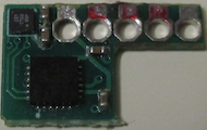
In my M5Stack Grey the two ICs (MPU6886 and BMM150) are on a small daughter board which was soldered to the underside of the Groove connector (GND, 5V, SDA, SCK). An additional pin provides 3.3V for the two ICs. But I am afraid the interrupt line coming out of the MPU6886 is not connected at all.
Please note: My M5Stack Grey board reads 2018.3, so maybe the daughter board was merged with the main board in later revisions?
Felix
Desoldered daughter board:
-
hey @davesee
I have the latest version of the M5Stack gray, but the board also reads 2018.3. I am going to try out your code that you used for M5StickC on my M5Stack Gray with PlatformIO.
I will report back how it went. All I want is a wake up on movement :). The same thing you got running on your M5StickC.
-
-
Not yet, but I will invest tomorrow the whole day and try to get his example working on the GREY.
I have the problem that the GREY just restarts on its own every few seconds. Looks like the GPIO35 is always triggering the wake up call from deep sleep. -
Hi @Tristar
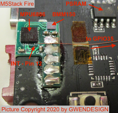
How's it going? My two M5Stack Gray and Fire did exactly the same, they would restart on their own. The reason is, as we already expected, that the interrupt output from the MPU6886 is not connected to the GPIO35 (at least not in my two M5Stacks).
I've fixed that by soldering a wire from MPU6886 pin12 (INT) to GPIO35 and now my M5Stacks properly go to sleep and only wakes up on motion again.
Cheers
Felix -
Hi @davesee
Thank you very much for your WOM code which I am using on my M5Stack Fire.
Just curious about the following code lines for WOM step 2:
- The read regdata are not actually used. Maybe by mistake?
- Comment says 32 samples, but actually only 16 samples are selected. Typo?
/* Step 2: Set Accelerometer LPF bandwidth to 218.1 Hz • In ACCEL_CONFIG2 register (0x1D) set ACCEL_FCHOICE_B = 0 and A_DLPF_CFG[2:0] = 1 (b001) */ I2C_Read_NBytes(MPU6886_ADDRESS, MPU6886_ACCEL_CONFIG2, 1, ®data); regdata = 0b00100001; // average 32 samples, use 218 Hz DLPF I2C_Write_NBytes(MPU6886_ADDRESS, MPU6886_ACCEL_CONFIG2, 1, ®data);Thanks
Felix -
@felmue
yeah, you are right. On the M5Stack Grey there is no wiring between the pins. Could you provide some images of the board where one can see how you did the soldering? time to rip my m5stack grey open and do some soldering too :)For the next version of the M5Stack there has definitelyto be a wiring between the IMU (mpu9250) and a pin like 35!!
-
Hi @Tristar
The daughter board with MPU6886 and BMM150 are the same for M5Stack Gray and Fire. So the picture I've attached to my previous post (#15) also applies for M5Stack Gray.
Good luck!
FelixP.S. you'll find the same information also through the link in my signature below.
-
Hi guys
Just a heads up on the new M5Core2 which has the IMU and mic on a micro board attached to the M5bus. As far as I can tell the interrupt pin of the MPU6886 doesn't seem to be connected to GPIO35 or any other pin on the M5bus which is a bit disappointing.
Cheers
Felix -
Does anyone know what the trigger values of registers ACCEL_WOM_THR represent? For example, for the ADXL345, 1 LSB of trigger register is the equalavent of 0.065 G. However, there is no information about this in the datasheet of the MPU6886 and the value also seem to be effected by setting a different value for A_DLPF_CFG in the ACCEL_CONFIG_2 register.
If anyone can help with this that would be nice.
-
@doublep hello, could you refer me to where you read that value from?
Hello! It looks like you're interested in this conversation, but you don't have an account yet.
Getting fed up of having to scroll through the same posts each visit? When you register for an account, you'll always come back to exactly where you were before, and choose to be notified of new replies (either via email, or push notification). You'll also be able to save bookmarks and upvote posts to show your appreciation to other community members.
With your input, this post could be even better 💗
Register Login