M5 POWER BANK with IP5108
-
Under this link IP3506 AUTOMATIC STANDBY was discussed the M5 Power Bank module.
Here is the inspiration from the realization of this module:-
Schema
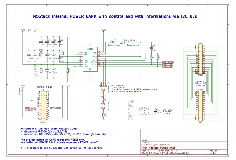
-
BOM
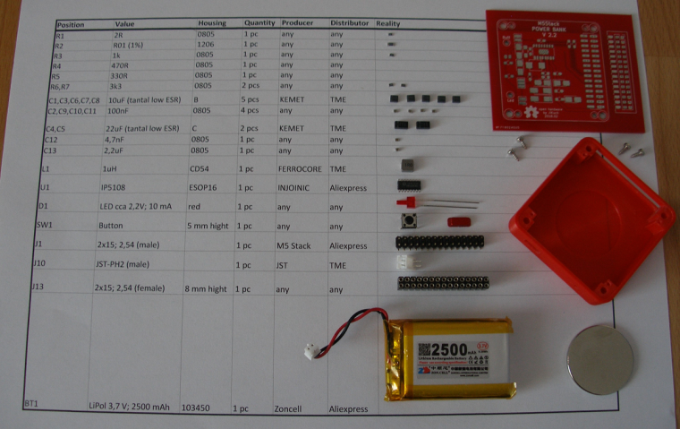
-
PCB for hand soldering
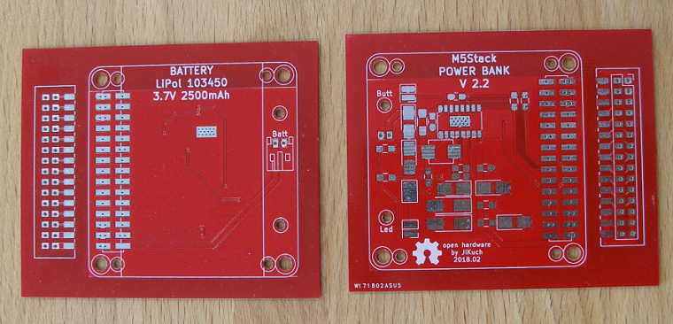
-
Case - 3D printed
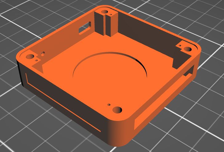
-
Final functional module
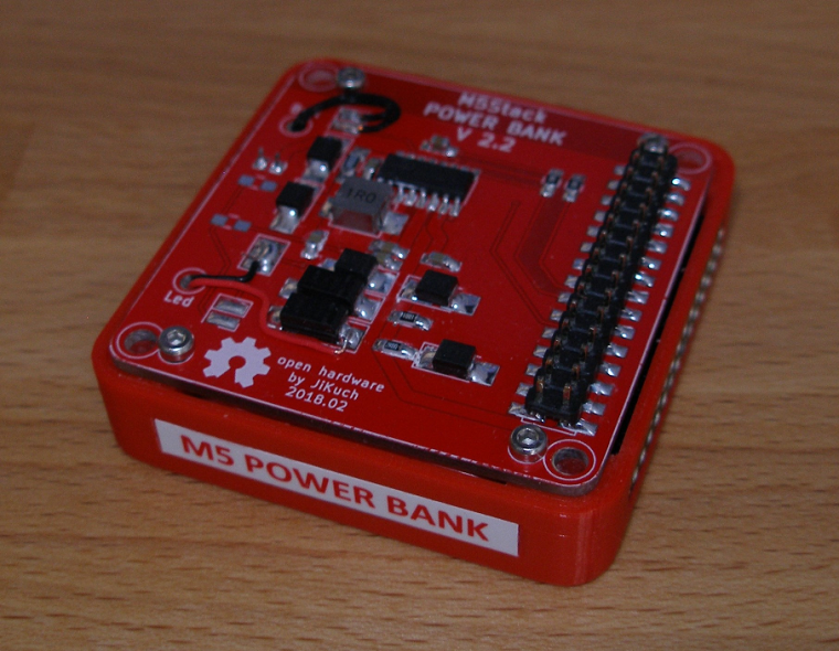
M5 Power Bank with IP5108 fully replaces M5 BOTTOM:
- The module also contains a magnet (big one)
- External M-bus (fully) is on the right side (female 2x15)
- LED indicator and On/Off button is on the left side
- LED functionality can be selected (5V, On/Off=IRQ, GPIO00 or GPIO01 software control)
- On/Off button functionality can also be programmed thru IP5108 registers
WARNING:
The module is designed to be connected directly to the M5 CORE because the components enter the space of M5 CORE! -
-
Nice desing jikuch.... I am trying to adapt it for a solar powered system, but am unable to find information in english about the ip5108 i2c register.
Could you help me?
Thanks -
IP5108 I2C description:
7-bit slave address IP5108 is 0x75 (byte with write bit = 0xEA; byte with read bit = 0xEB)
400 Kbps speed of I2C supported
1 byte data = 8-bit data (bits from 7 to 0)WRITE Arduino example:
Wire.beginTransmission(0x75);
Wire.write(register_address_byte);
Wire.write(data_byte);
Wire.endTransmission();READ Arduino example:
Wire.beginTransmission(0x75);
Wire.write(register_address_byte);
Wire.endTransmission();
Wire.requestFrom(0x75,1);
data_byte = Wire.read();REGISTERS:
1. Enable / disable functions:
SYS_CTL0 = 0x01:- bit 4 (read/write): 0 = disbale / 1 = enable (1 = after reset) detection ??? (I do not understand.)
- bit 3 (read/write): 0 = disbale / 1 = enable (1 = after reset) light
- bit 2 (read/write): 0 = disbale / 1 = enable (1 = after reset) booster
- bit 1 (read/write): 0 = disable / 1 = enable (1 = after reset) charger
SYS_CTL1 = 0x02:
- bit 1 (read/write): 0 = disable / 1 = enable (1 = after reset) auto-standby
- bit 0 (read/write): 0 = disable / 1 = enable (1 = after reset) auto ??? (I do not understand.)
SYS_CTL3 = 0x03:
- bit 5 (read/write): 0 = disable / 1 = enable (1 = after reset) off by button
2. General setup features:
SYS_CTL2 = 0x0C:- bits 7-3 (read/write): (01010 = after reset) auto-standby current limit as multiple 12 mA
SYS_CTL4 = 0x04:
- bits 7-6 (read/write): (10 = after reset) time for auto-standby: 00=8s, 01=16s, 10=32s, 11=64s
SYS_CTL3 = 0x03:
- bits 7-6 (read/write): (01 = after reset) time for recognition button press: 00=1s, 01=2s, 10=3s, 11=4s
SYS_CTL5 = 0x07:
- bit 1 (read/write): (0 = after reset) control of light by button: 0=press, 1=double click
- bit 0 (read/write): (0 = after reset) off by button: 0=double click, 1=press
3. Charging setup features:
CHARGER_CTL1 = 0x22:- bits 3-2 (read/write): (01 = after reset) VOUT undervoltage limit during chargig: 00=4.53V, 01=4.63V, 10=4.73V, 11=4.83V
CHARGER_CTL2 = 0x24:
- bits 6-5 (read/write): (00 = after reset) battery type = charging voltage: 00=4.2V, 01=4.3V, 10=4.35V
- bits 2-1 (read/write): (10 = after reset) overcharging of charging: 00=0mV, 01=14mV, 10=28mV, 11=42mV
CHG_DIG_CTL4 = 0x25:
- bits 4-0 (read/write): (10110 = after reset) charging current setting [A]:
b0 x 0.1 + b1 x 0.2 + b2 x 0.4 + b3 x 0.6 + b4 x 1.4
4. Charging information:
Reg_READ0a = 0x70:- bit 3 (read only): charging status: 0 = not charging, 1 = charging
Ref_READ0b = 0x71:
- bits 7-5 (read only): detailed charging status:
000 = inactivity
001 = charging
010 = constant current charging
011 = charging with constant voltage
100 = ??? (missing description in original document)
101 = end of charging (maintenance current) - bit 3 (read only): signal of end of charging (=1)
5. PIN assignment & control:
MFP_CTL0 = 0x51:- bits 5-4 (read/write): (00 = after reset) pin LIGHT assignement: 00=WLED, 01=GPIO2, 10=VREF
- bits 3-2 (read/write): (00 = after reset) pin L4 assignement: 00=L4, 01=GPIO1
- bits 1-0 (read/write): (00 = after reset) pin L3 assignement: 00=L3, 01=GPIO0
GPIO_CTL2a = 0x53:
- bits 2-0 (read/write): (000 = after reset) GPIO[2:0] input enable
GPIO_CTL2b = 0x54:
- bits 2-0 (read/write): (000 = after reset) GPIO[2:0] output enable
GPIO_CTL3 = 0x55:
- bits 2-0 (read/write): (000 = after reset) GPIO[2:0] data
6. Measurement:
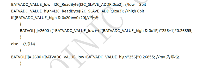
BATVADC_DAT0 = 0xA2:- pins 7-0 (read only): LOW 8 bits (byte) of BATVADC
BATVADC_DAT1 = 0xA3:
- pins 5-0 (read only): HIGH 6 bits of BATVADC
Calculation according to the original document:
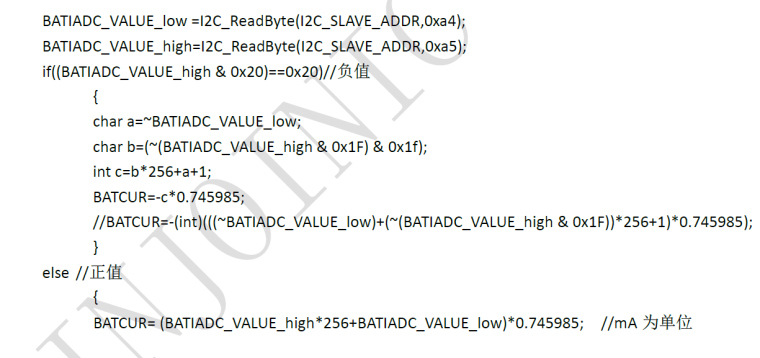
BATIADC_DAT0 = 0xA4:
- pins 7-0 (read only): LOW 8 bits (byte) of BATIADC
BATIADC_DAT1 = 0xA5:
- pins 5-0 (read only): HIGH 6 bits of BATIADC
Calculation according to the original document:
BATOCV_DAT0 = 0xA8:
- pins 7-0 (read only): LOW 8 bits (byte) of BATOCV
BATOCV_DAT1 = 0xA9:
- pins 5-0 (read only): HIGH 6 bits of BATOCV
Calculation according to the original document:
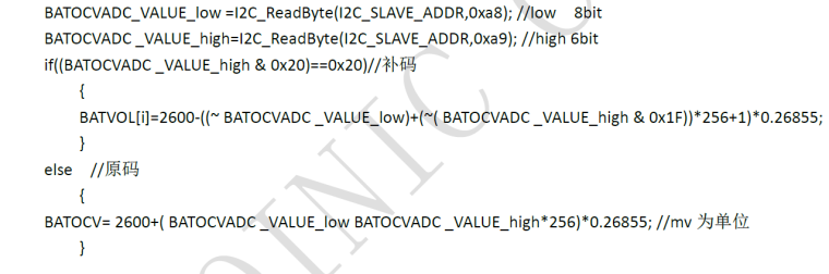
This is true: BATOCV = BATVACD + BATIADC * battery_internal_resistnace
7. WLED status:
Reg_READ1 = 0x72:- bit 7 (read only): 0 = WLED is off, 1 = WLED is on
8. Light / heavy load:
Reg_READ1 = 0x72:- bit 6 (read only): 0 = heavy load over 75 mA, 1 = light load less 75 mA
9. Button control:
Reg_READ2 = 0x77:- bit 3 (read; write 1 = reset) flag button double clicked (=1)
- bit 1 (read; write 1 = reset) flag button pressed (=1)
- bit 0 (read; write 1 = reset) flag button clicked (=1)
That is all.
-
@jikuch Nice design.
Do you have the I2C register document of IP5108? Could you share it? Thanks! -
Hi, can somebody tell me: if I change something in ip5108 through i2c, will it be saved, or i must make this changes each time when i start device?
-
Hi, can you tell me: if I change something in ip5108 through i2c (for example disable auto-standby), will this changers be saved, or i must make this changes (with software) each time when i start device?