ADC-Unit, major problem
-
There is a major problem when connecting a ADC-Unit through a PaHUB. The i2c pull-up resistors inside the unit cause an unintentional increasing from the 3.3V internal supply voltage. Because the reference of the ADS1100 depents on this 3.3V supply the output of the ADS1100 varies.
The difference in output value, when the unit is directly connected tot an M5Stack or via a PaHUB, is about 17%.In other words, the unit is useless when connected via a PaHUB and possible also when multiple i2c devices are conncted on the same bus (untested).
My suggestion is to connect both the pull-up resistors inside the unit to 5V.
Anyone has a better solution? -
@hazo
Did some test with the ADC-Unit connected to a M5Stack Gray via a passive Hub instead of the active Hub in my previous posting:
ADC-unit connected via a passive (Grove) HUB: input voltage is 1.00V, ADC-Unit output is 2501.
Also connect a DAC to the passive HUB: ADC-Unit output is 2465.
Also connect a Joystick unit to the bus: ADC-Unit output is 2335.
These results are worrying... -
@hazo
To solve the problem I connected the two internal i2c pull-up resistors to 5V. You need steady hands to cut the copper layer between R3 and C1.When done, solder a wire between R3 and 5V (on connector J1).
That's all ;-)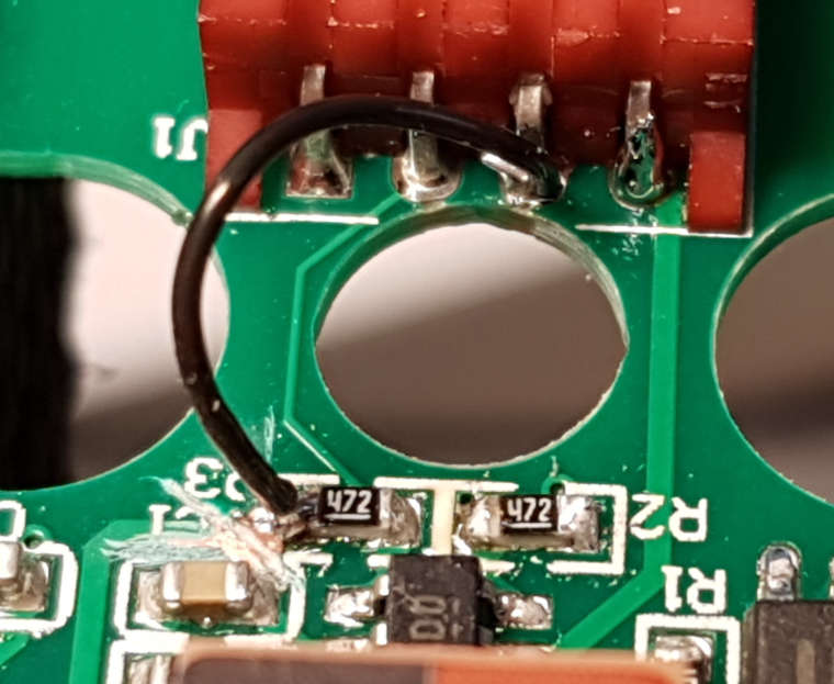
-
R Richelieu referenced this topic on
Hello! It looks like you're interested in this conversation, but you don't have an account yet.
Getting fed up of having to scroll through the same posts each visit? When you register for an account, you'll always come back to exactly where you were before, and choose to be notified of new replies (either via email, or push notification). You'll also be able to save bookmarks and upvote posts to show your appreciation to other community members.
With your input, this post could be even better 💗
Register Login