SIM7020G echoing even after using ATE0
-
Greetings,
I am getting started with SIM7020G COM.X NB-IOT module. Currently, I am interfacing this module with STM32 microcontroller.
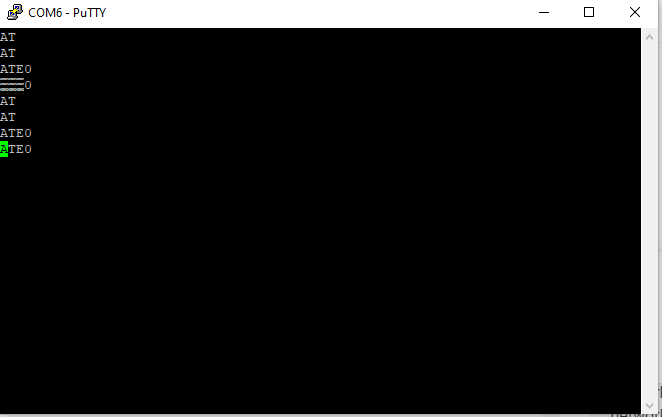
Issue is that I am getting echo while transmitting AT command using STM32 UART. After some quick search I found that echoing can be turned OFF using "ATE0" AT command; So I tried that command but still facing same issue.
Command which I send is not being recognized as I sent reboot command but it doesn't work.
Baudrate:
I have tried 9600,115200,38400 but got the same result.Length of cable & terminal software:
I also tried various Serial terminal software to transmit AT command via PC. cable length between Tx-Rx pin is hardly 10cm (using female-male jumper cable).Power supply:
I am powering SIM7020G with 5V-1A supply and tried USB supply directly to that green PCB on module too.Network status LED:
network status LED is blinking every second. I know that means module is not connected to network but atleast I should get response from SIM7020G.I appreciate any kind of help.
Thank you so much for your time & efforts.
Note: I also tried AT&W command to save settings after using ATE0 command.
-
Hello @jeetS
are you sure the echo is from the SIM7020G? I wonder if your PuTTY has local echo enabled. What happens if you disconnect TX and RX lines? If you still see the echo it's the local echo.
In the COM.X module you also need to double check the DIP switches for TX and RX. I don't remember what the default settings are.
BTW: default baudrate is 115200.
Thanks
Felix -
Hey, Thanks for quick response.
by default pin number 5 and 13 are Rx/Tx pin. Yes, I tried removing Rx and Tx connection and it shows no response. So, it is not echo from PuTTY.
I have tried using 115200 baud-rate and it is not working. Rx/Tx pins are connected properly.
I have also tried AT commands after removing SIM card.
Do you have any idea what should I do next? what if this is firmware issue? Do I even need firmware/firmware update? :(
-
Hello @jeetS
I may have misspoken - according to the SIM7020 AT command documentation the baudrate is auto-bauding as a factory default. So after power-up of the modem the first "AT" sent to it is used to detect the baudrate of the sender.
What I do not understand is that you'll get the AT command echoed, but not confirmed. When "AT" is sent to the modem it should respond with "AT" and then "OK".
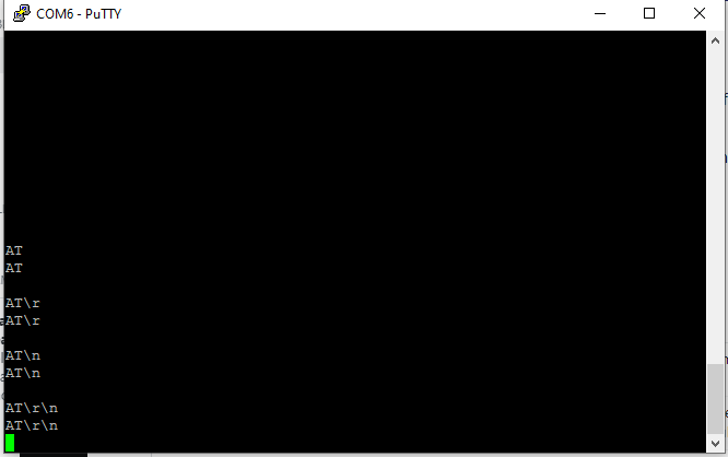
Maybe the line ending is the issue here? I have the best result with only using a carriage return. Eg. "AT\r".
Check in PuTTY and try the different line endings.
I don't think it is a firmware issue and w/o getting a proper response from the modem you don't even know which firmware version is currently installed.
Thanks
Felix -
Thank you for response.
Okay, I will try what you have suggested. yes, I also noticed that SIM7000 series has autobauding functionality.
I will let you know what if this resolves issue.
Thank you
-
Hi there,
I have tested CR,LF and EOL in the end but still getting same issue.
I tried to connect it with easyloader application but it shows "failed". I tried both 1500000 and 115200 baudrate.
What if I upload any latest firmware to sim7020G?
-
Hello @jeetS
no, I meant to change the line end in PuTTY settings. E.g. what happens if you press the enter key. See screenshot here. You might need to scroll down a bit to see the screen shot.
"\r" etc. is meant for when you send an AT command from within a program. A carriage return is normally not visible in the PuTTY terminal.
Thanks
Felix -
Oh Okay. Let me try
I think I should also include these points.
-
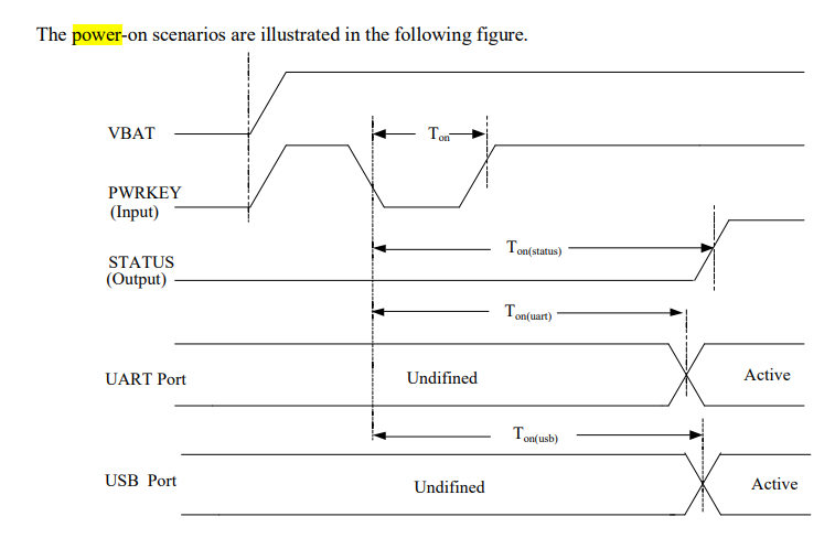
Do I need to connect POWERKEY to STM32 controller GPIO and Pull down it as mentioned in datasheet? (See below attached image)
-
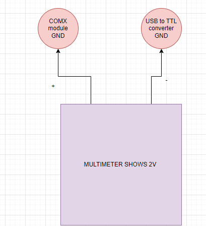
I only connect Tx/Rx in USB to TTL convert as there is 2V difference between GND of COM.X module and USB to TTL converter.
PS: I tried settings in PuTTY but it is not working.
Thank you so much felix for support!
-
-
UPDATE:
I tried AT+CPOWD=0 command and netlight stopped blinking. So, I am guessing command is being sent and accepted by SIM.
and also it can be turned on using AT+CFUN=1 command.
-
@jeets said in SIM7020G echoing even after using ATE0:
UPDATE:
I tried AT+CPOWD=0 command and netlight stopped blinking. So, I am guessing command is being sent and accepted by SIM.
and also it can be turned on using AT+CFUN=1 command.
However, I am still getting echo in response. How can I get "OK" or "ERROR" or something else?
I don't understand why this is happening. I am using this USB to TTL converter. I changed converters too.
It is not possible to troubleshoot or program efficiently without proper responses from SIM7020G.
Thank you. -
Hello @jeetS
a blinking netlight means the modem is (already) turned on (at least that is my experience). You need to take into account that there already is some logic on the green board regarding POWERKEY (no schematic available unfortunatley) and some additional logic on the carrier board. See schematic here.
Regarding the USB TTL converter: as long as it is set / using 3.3 V towards the COM.X module you should be fine.
Maybe try an ATZ0 to restore default settings.
Thanks
Felix -
Hello @jeetS
I did some experiment using an USB to TTL converter (set to 3.3 V) and I think you are missing a common GND connection.
When I only connect TX and RX (but no common GND) I get exactly what you are seeing. The "AT" is echoed, but no "OK" or "ERROR" is returned.
So make sure you have TX, RX and GND connected between USB TTL converter and COM.X module.
Thanks
Felix -
I tried to connect the ground but the problem is there is 2V difference between Ground of USB to TTL converter and Ground of COM.X module.
How should I remove it?
Thank you
-
@jeets said in SIM7020G echoing even after using ATE0:
I tried to connect the ground but the problem is there is 2V difference between Ground of USB to TTL converter and Ground of COM.X module.
How should I remove it?
I connected Green PCB and USB to TTL converter with PC (Supplying voltage via USB connector)
I am able to ON/OFF SIM7020G using AT commands but I am not getting any response in PuTTY. There are no echo in UART but also no response from SIM7020G.
I measured voltage over Tx pin of SIM7020G and its 0.9V.
Observation:
I can see both TX and RX LED blinking on my USB to TTL converter whenever I send command but not receiving data on serial monitor.
I have tried different baudrate but the issue is not solved.
Thank you so much to put your efforts and time felix!
-
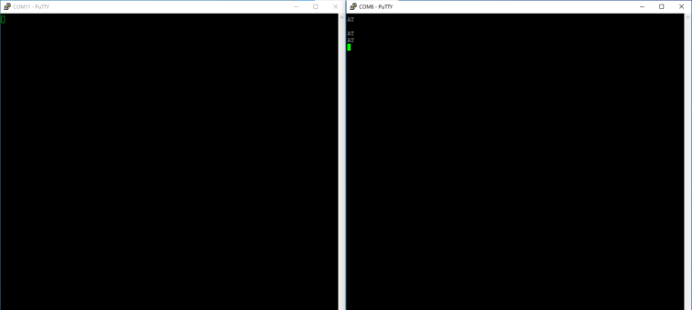
I connected to two USB to TTL converter. One to transmit data and another one to receive the data.
and opened two different serial terminal in PuTTY.TX LED of one converter and RX LED for another converter is still blinking but there are no data on PuTTY terminal
I also used tera term and Terminal software to verify it.
-
Hello @jeetS
can you explain what you mean about the 2 V difference?
The USB to TTL converter I use can be switched between 5 V and 3.3 V and I set it to 3.3 V.
Is your USB to TTL converter switched to 3.3 V (or a 3.3 V version)?
In my test case (when GND is not connected) TX and RX LED both blink as well. That is because RX is floating and picking up whatever TX is sending. That is (I think) creating the echo you are seeing.
Thanks
Felix -
Thanks for quick response.
when I was measuring voltage between GND of USB to TTL converter and GND of COM.X module. Multimeter shows 2V. (See the illustration)
But this issue is resolved by supplying power to same power source (My PC).
I want add that when I use two different USB to TTL converters then RX LED is not blinking and that means i am not getting any response.
I think this is due to Rx pin HIGH is 1.7V only and my USB to TTL converter (using CP2102) is not recognizing 1.7V. (Just a guess)
Can you share the converter you are using?
-
Hello @jeetS
without a common GND, e.g. COM.X GND not connected to USB to TTL GND and then measuring the voltage between the two is not very useful in most cases. That is why, when two circuits which are powered from different power sources, a common GND is required.
Anyhow if you power COM.X without RX connected to anything and then measure between RX and GND and you only get 1.7 V then yes, that is probably too low.
If I do the same then I get 3.3 V between RX and GND.
I use this USB TTL converter set to 3.3 V.
Maybe this article about common ground can help.
Thanks
Felix -
Hi there,
Now, Module is working correctly there were few issues and solved it step by step. This solution is for someone if they found this post & they need help.
- USB to TTL convert was not recognizing UART signals transmitted from SIM7020G module. (as it was 1.7V)
- GND was missing between different module (MOST IMP) (Use common supply maybe PC, SMPS or something else)
- CR should be there after command.
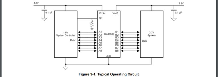
What I did is add Logic Level Converter module between USB to TTL converter and SIM7020G module.
NOTE: Refer datasheet of IC and do the same connection as shown in datasheet for less garbage data and proper communication.
Thank you so much Felix for your help and efforts.
-
Hello @jeetS
you are welcome. I am glad to hear you got it working to your liking. And thank you for letting me/us know and for the detailed step by step explanation.
Thanks
Felix
Hello! It looks like you're interested in this conversation, but you don't have an account yet.
Getting fed up of having to scroll through the same posts each visit? When you register for an account, you'll always come back to exactly where you were before, and choose to be notified of new replies (either via email, or push notification). You'll also be able to save bookmarks and upvote posts to show your appreciation to other community members.
With your input, this post could be even better 💗
Register Login