There is no socket for Atom module.
I could not comfortably use the product without
complete information!
Posts made by Kabron
-
Atom Joystick Schematic is incomplete!posted in Atom
-
RE: M5 DAPLink as debuggerposted in Modules
No, it can not.
So, the benefit is very questionable...Also, the current FW is very fragmental
-
RE: ESP32 Arduino vs M5Stack Arduinoposted in Arduino
@teastain said in ESP32 Arduino vs M5Stack Arduino:
Кстати:
Какую версию Arduino IDE вы используете?Does not matter. Same for 2.3.4.
-
ESP32 Arduino vs M5Stack Arduinoposted in Arduino
If you are going to define M5 family board in Board Manager, you'll have to choose between two separate variants:
ESP32 Arduino and M5Stack Arduino.
See the screenshots.These variants are not the same but quite different.
And compilation results also different.
As I partially understand the first variant will works with mostly ESP32 libraries,
while the second one will use M5Stack oriented libraries.Are there gurus who can describe in details these differences?


-
M5Core2 and M5StickC AXP192 libraries: which one is more Reliable?posted in Modules
I noticed that theese libs are significatelly different and realised different functions. Which one should I use to get the most functional AXP192 control?
-
RE: M5StickC-Plus2 Battery Voltage Measuring Issue when Radio ONposted in Modules
I guess, this is a possible solution for longer battery use.

-
RE: M5StickC-Plus2 Battery Voltage Measuring Issue when Radio ONposted in Modules

Here is discharge curve with 0.8V correction.
Correction could not be done easily by substracting the error, because below Battery voltage 3.5V, measurement begins rapidly grow. Device stops work at 3.4V.It is difficult to name this device as a successful design.
-
M5StickC-Plus2 Battery Voltage Measuring Issue when Radio ONposted in Modules
Measured values are approximatelly 0.8V greater when WiFi or BT are used.
-
RE: Upload M5StickC Schematicposted in Official Updates
@ajb2k3 I see no answer to my question in this site. Maybe you could?
-
RE: M5StickC : how to switch 5V out off?posted in M5 Stick/StickC
@felmue I draw schematic above from my exemplar. Obviously it's too old.
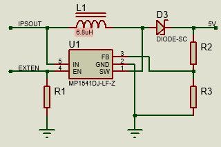
IC is SOT-23-5 and its marking corresond with MP1541 datasheet.The root of the evil is M5STACK's absolutely lackadaisical documentation for all the products.
-
RE: M5StickC : how to switch 5V out off?posted in M5 Stick/StickC
Definitelly, M5SticC and M5SticC Plus have different schematics. DC-Boost in M5SticC Plus is sgm6603-5.
-
RE: M5StickC : how to switch 5V out off?posted in M5 Stick/StickC
So, according to schematic switching off 5V is fundamentally impossible. IPSOUT via L1 and D3 allways present at output.
-
RE: Upload M5StickC Schematicposted in Official Updates
It's not a Schematic, it's a parody of a Schematic. Shame!
What is part # of DC-Boost IC for 5V out???
-
RE: M5StickC : how to switch 5V out off?posted in M5 Stick/StickC
@felmue I tested it:
void AXP192::SetPeripherialsPower(uint8_t state) {
if (!state){
Write1Byte(0x10, Read8bit(0x10) & 0XFB);
Write1Byte(0x12, Read8bit(0x12) & 0XBF);
}
else if (state) {
Write1Byte(0x10, Read8bit(0x10) | 0X04);
Write1Byte(0x12, Read8bit(0x12) | 0X40);
}EXT_BOOST_EN controlled correctly, DC-Boost stops generating, but bypassed input Vbatt to 5V output.
What an idiot designed this part of schematic?
I could not identify DC-Boost IC(Sot-23-5 marked IB3KB)/
-
RE: M5StickC : how to switch 5V out off?posted in M5 Stick/StickC
@felmue It only switched 5V to Vbatt
I see the only way to reconnect EXT_BOOST_EN of the BOOST converter to VESP_3V3. -
RE: M5StickC : how to switch 5V out off?posted in M5 Stick/StickC
I tested it - does not work at all
