WIP ACSSR Guide
-
I can't get RS485/Modbus working and so here is the Work in Progress ACSSR Guide.
https://www.hackster.io/AJB2K3/get-started-with-the-m5stack-acssr-cf960b -
Hello @ajb2k3
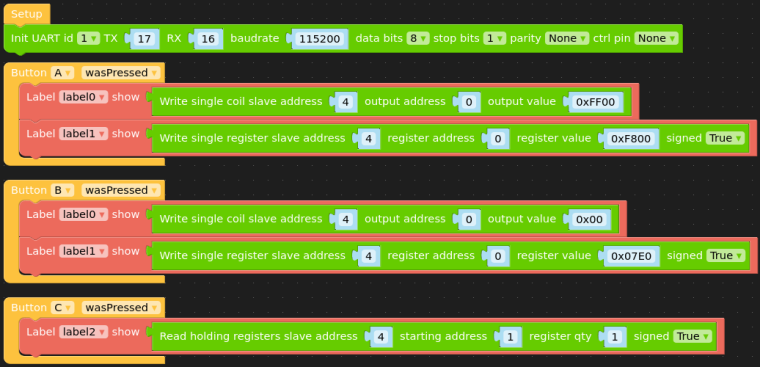
for your excellent ACSSR guide you'll find below the UIFlow Modbus blocks to switch the ACSSR on / off (together with the RGB LED) using an M5Stack Basic.
Two things to note which were not obvious to me:
- Baudrate needs to be
115200(anything lower only resets the ACSSR) - to turn the ACSSR
onthe value needs to be0xFF00(See here)
Button functions:
- Button A: relay on / LED red
- Button B: relay off / LED green
- Button C: read version
and the corresponding Python code:
from m5stack import *
from m5ui import *
from uiflow import *
from modbus.master.uModBusSerial import uModBusSerial

setScreenColor(0x222222)

label0 = M5TextBox(54, 58, "label0", lcd.FONT_Default, 0xFFFFFF, rotate=0)
label1 = M5TextBox(54, 100, "label1", lcd.FONT_Default, 0xFFFFFF, rotate=0)
label2 = M5TextBox(50, 140, "label2", lcd.FONT_Default, 0xFFFFFF, rotate=0)

def buttonA_wasPressed():
  # global params
  label0.setText(str(modbus.write_single_coil(4, 0, 0xFF00)))
  label1.setText(str(modbus.write_single_register(4, 0, 0xF800, True)))
  pass
btnA.wasPressed(buttonA_wasPressed)

def buttonC_wasPressed():
  # global params
  label2.setText(str(modbus.read_holding_registers(4, 1, 1, True)))
  pass
btnC.wasPressed(buttonC_wasPressed)

def buttonB_wasPressed():
  # global params
  label0.setText(str(modbus.write_single_coil(4, 0, 0x00)))
  label1.setText(str(modbus.write_single_register(4, 0, 0x07E0, True)))
  pass
btnB.wasPressed(buttonB_wasPressed)

modbus = uModBusSerial(1, tx=17, rx=16, baudrate=115200, data_bits=8, stop_bits=1, parity=None, ctrl_pin=None)
Thanks
FelixGPIO translation table M5Stack / M5Core2
Information about various M5Stack products.
Code examples - Baudrate needs to be
-
@felmue said in WIP ACSSR Guide:
Hello @ajb2k3
for your excellent ACSSR guide you'll find below the UIFlow Modbus blocks to switch the ACSSR on / off (together with the RGB LED) using an M5Stack Basic.
Two things to note which were not obvious to me:
- Baudrate needs to be
115200(anything lower only resets the ACSSR) - to turn the ACSSR
onthe value needs to be0xFF00(See here)
Button functions:
- Button A: relay on / LED red
- Button B: relay off / LED green
- Button C: read version
and the corresponding Python code:
from m5stack import *
from m5ui import *
from uiflow import *
from modbus.master.uModBusSerial import uModBusSerial

setScreenColor(0x222222)

label0 = M5TextBox(54, 58, "label0", lcd.FONT_Default, 0xFFFFFF, rotate=0)
label1 = M5TextBox(54, 100, "label1", lcd.FONT_Default, 0xFFFFFF, rotate=0)
label2 = M5TextBox(50, 140, "label2", lcd.FONT_Default, 0xFFFFFF, rotate=0)

def buttonA_wasPressed():
  # global params
  label0.setText(str(modbus.write_single_coil(4, 0, 0xFF00)))
  label1.setText(str(modbus.write_single_register(4, 0, 0xF800, True)))
  pass
btnA.wasPressed(buttonA_wasPressed)

def buttonC_wasPressed():
  # global params
  label2.setText(str(modbus.read_holding_registers(4, 1, 1, True)))
  pass
btnC.wasPressed(buttonC_wasPressed)

def buttonB_wasPressed():
  # global params
  label0.setText(str(modbus.write_single_coil(4, 0, 0x00)))
  label1.setText(str(modbus.write_single_register(4, 0, 0x07E0, True)))
  pass
btnB.wasPressed(buttonB_wasPressed)

modbus = uModBusSerial(1, tx=17, rx=16, baudrate=115200, data_bits=8, stop_bits=1, parity=None, ctrl_pin=None)
Thanks
FelixThanks but can't get it to work on a core2 using the RS485 unit
- Baudrate needs to be
-
Hello @ajb2k3
I've just checked. Above blocks work for me with an M5Core2 as well. Instead of TX=17 / RX=16 I use TX=14 / RX=13. That said I do not have the RS485 unit so I am using the little RS485 board (which came with the LAN module) albeit outside the LAN module connected via a BUS module.
The ACSSR is powered from an external 12 V power supply. The little RS485 board is powered with 5 V from the M5Core2. There are only two wires between the ACSSR and the little RS485 board: A <-> A and B <-> B. I also added an 120 Ohm resistor between A and B of the little RS485 board. The ACSSR already has that resistor in place internally.
Thanks
Felix
Hello! It looks like you're interested in this conversation, but you don't have an account yet.
Getting fed up of having to scroll through the same posts each visit? When you register for an account, you'll always come back to exactly where you were before, and choose to be notified of new replies (either via email, or push notification). You'll also be able to save bookmarks and upvote posts to show your appreciation to other community members.
With your input, this post could be even better 💗
Register Login