POECAM and PIR sensor
-
Apologies for what will probably be a very basic question.
I have recently got my POECAM working with Arduino IDE and an trying to read the sensor value from a [PIR sensor] (https://shop.m5stack.com/products/pir-module).
I have read through the scare documention that is available for this device and am at a lose where to start I tried dumping the GPIO pins to serial as I hold my hand over the sensor and inferring which pin was the sensor; but I am guessing that a pin needs to be powered or in read mode as no change occurs ?
void setup() { Serial.begin(115200); } void loop() { for(int i=0;i<40;i++) { int pin = digitalRead(i); Serial.print(i); Serial.print(':'); Serial.print(pin); Serial.print('|'); } Serial.println(' '); } -
Hello @nemsys
have a look at the PIR example. Also keep in mind that according to the documentation it can take up to 2 s for the PIR to react: "Notice: This Unit has 2s delay time."
Thanks
Felix -
hi @felmue
I had tried to compile the PIR example sketch after installing the libraries but I get the following compile error
Arduino/libraries/M5Stack/src/M5Stack.h:112,
Projects/ESP32/M5Stack/examples/Unit/PIR/PIR.ino:16:
.arduino15/packages/m5stack/hardware/esp32/2.0.7/libraries/SD/src/SD.h:31:30: error: 'SS' was not declared in this scope
     bool begin(uint8_t ssPin=SS, SPIClass &spi=SPI, uint32_t frequency=4000000, const char * mountpoint="/sd", uint8_t max_files=5, bool format_if_empty=false);
                              ^~
.arduino15/packages/m5stack/hardware/esp32/2.0.7/libraries/SD/src/SD.h:31:30: note: suggested alternative: 'FS'
     bool begin(uint8_t ssPin=SS, SPIClass &spi=SPI, uint32_t frequency=4000000, const char * mountpoint="/sd", uint8_t max_files=5, bool format_if_empty=false);
                              ^~
                              FS
Multiple libraries were found for "SD.h"
  Used: .arduino15/packages/m5stack/hardware/esp32/2.0.7/libraries/SD
  Not used: .arduino15/libraries/SD
Do we know if the stock M5Stack headers are compatabile with this board ?
the ethernet example for the cam-timer board compiles and runs without issue but notably it doesn't make use of the M5Stack header
ethernetStream sketch headers
#include <WiFi.h>
#include "esp_task_wdt.h"
#include "esp_camera.h"
#include "PoE_CAM.h"
#include <esp_heap_caps.h>
PoE_Cam.h
#include "./utility/camera_index.h"
#include "./utility/w5500_image.h"
#include "./utility/uart_frame.h"
#include "./utility/timer_cam_config.h"
#include "./utility/cam_cmd.h"
#include "./utility/protocol.h"
#include "./utility/app_httpd.h"
#include "./utility/network.h"
#include "./utility/image_post.h"
I'm not being foolish the wiring is as simple as (ignore the solder) :
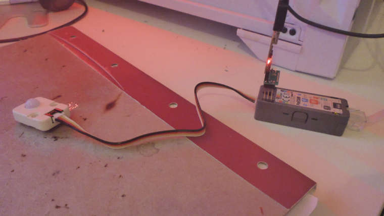
-
Hello @nemsys
you'll only need the part setting up the input pin in setup():
pinMode(33, INPUT);and the part in loop() which reads it:
if (digitalRead(33) == 1)
{
  Serial.println("Sensing");
} else {
  Serial.println("Not Sensed");
}
delay(500);
You can ignore the rest which mostly deals with the LCD the POECAM doesn't have.
Thanks
Felix -
HI @felmue ,
Thankyou for your reply :)
I had already striped the LCD code its the M5Stack header (and includes) itself that doesn't want to compile.
The only samples that compile are the factory test and Ethernet stream which leads me to believe their isn't a board specific header as such.
digging through the platform library there is a pin_header
#ifndef Pins_Arduino_h
#define Pins_Arduino_h

#include <stdint.h>

#define EXTERNAL_NUM_INTERRUPTS 16
#define NUM_DIGITAL_PINS        40
#define NUM_ANALOG_INPUTS       16

#define analogInputToDigitalPin(p)  (((p)<20)?(esp32_adc2gpio[(p)]):-1)
#define digitalPinToInterrupt(p)    (((p)<40)?(p):-1)
#define digitalPinHasPWM(p)         (p < 34)

static const uint8_t TX = 1;
static const uint8_t RX = 3;

static const uint8_t SDA = 25;
static const uint8_t SCL = 33;

static const uint8_t G23 = 23;
static const uint8_t G25 = 25;
static const uint8_t G27 = 27;
static const uint8_t G22 = 22;
static const uint8_t G26 = 26;
static const uint8_t G21 = 21;
static const uint8_t G32 = 32;
static const uint8_t G35 = 35;
static const uint8_t G34 = 34;
static const uint8_t G5 = 5;
static const uint8_t G39 = 39;
static const uint8_t G18 = 18;
static const uint8_t G36 = 36;
static const uint8_t G19 = 19;
static const uint8_t G15 = 15;

static const uint8_t G2 = 2;
static const uint8_t G33 = 33;

static const uint8_t G13 = 13;
static const uint8_t G4 = 4;

static const uint8_t G0 = 0;

static const uint8_t DAC1 = 25;
static const uint8_t DAC2 = 26;

static const uint8_t ADC1 = 35;
static const uint8_t ADC2 = 36;

#endif /* Pins_Arduino_h */
which of course is one of the many reasons why the example library doesn't compile,my device simply has different pins.
In the factory test I see the references to UART Ext_PIN_1 and Ext_PIN_2 :
  Serial.println("UART INIT");
  uart_init(Ext_PIN_1, Ext_PIN_2);
which is defiend in timer_cam_config.h
#define Ext_PIN_1 33
#define Ext_PIN_2 25
So lets strip off the header and run it with the pure Arduino.
#include <Arduino.h>

void setup() {

   pinMode(33, INPUT_PULLUP);
   Serial.begin(115200);
}

void loop() {

   Serial.println(digitalRead(33));
   delay(1000);
}
It works but only if I set the board to M5Stack-Timer-CAM.
Additionally the Ethernet-Stream example needs the network.h header lines 16-17 altered as below else it will not compile
static ip4_addr_t ip_addr; // For platform = espressif32@ ^3.5.0
//static esp_ip4_addr_t ip_addr; // For platform = espressif32@ ^5.1.0
I will post this in the modules forum for other users trying to build the examples, apologies for putting this in FAQ (it was late/early)
Hello! It looks like you're interested in this conversation, but you don't have an account yet.
Getting fed up of having to scroll through the same posts each visit? When you register for an account, you'll always come back to exactly where you were before, and choose to be notified of new replies (either via email, or push notification). You'll also be able to save bookmarks and upvote posts to show your appreciation to other community members.
With your input, this post could be even better 💗
Register Login