SIM7020G echoing even after using ATE0
-
@jeets said in SIM7020G echoing even after using ATE0:
UPDATE:
I tried AT+CPOWD=0 command and netlight stopped blinking. So, I am guessing command is being sent and accepted by SIM.
and also it can be turned on using AT+CFUN=1 command.
However, I am still getting echo in response. How can I get "OK" or "ERROR" or something else?
I don't understand why this is happening. I am using this USB to TTL converter. I changed converters too.
It is not possible to troubleshoot or program efficiently without proper responses from SIM7020G.
Thank you. -
Hello @jeetS
a blinking netlight means the modem is (already) turned on (at least that is my experience). You need to take into account that there already is some logic on the green board regarding POWERKEY (no schematic available unfortunatley) and some additional logic on the carrier board. See schematic here.
Regarding the USB TTL converter: as long as it is set / using 3.3 V towards the COM.X module you should be fine.
Maybe try an ATZ0 to restore default settings.
Thanks
Felix -
Hello @jeetS
I did some experiment using an USB to TTL converter (set to 3.3 V) and I think you are missing a common GND connection.
When I only connect TX and RX (but no common GND) I get exactly what you are seeing. The "AT" is echoed, but no "OK" or "ERROR" is returned.
So make sure you have TX, RX and GND connected between USB TTL converter and COM.X module.
Thanks
Felix -
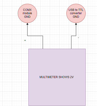
I tried to connect the ground but the problem is there is 2V difference between Ground of USB to TTL converter and Ground of COM.X module.
How should I remove it?
Thank you
-
@jeets said in SIM7020G echoing even after using ATE0:
I tried to connect the ground but the problem is there is 2V difference between Ground of USB to TTL converter and Ground of COM.X module.
How should I remove it?
I connected Green PCB and USB to TTL converter with PC (Supplying voltage via USB connector)
I am able to ON/OFF SIM7020G using AT commands but I am not getting any response in PuTTY. There are no echo in UART but also no response from SIM7020G.
I measured voltage over Tx pin of SIM7020G and its 0.9V.
Observation:
I can see both TX and RX LED blinking on my USB to TTL converter whenever I send command but not receiving data on serial monitor.
I have tried different baudrate but the issue is not solved.
Thank you so much to put your efforts and time felix!
-
I connected to two USB to TTL converter. One to transmit data and another one to receive the data.
and opened two different serial terminal in PuTTY.TX LED of one converter and RX LED for another converter is still blinking but there are no data on PuTTY terminal
I also used tera term and Terminal software to verify it.

-
Hello @jeetS
can you explain what you mean about the 2 V difference?
The USB to TTL converter I use can be switched between 5 V and 3.3 V and I set it to 3.3 V.
Is your USB to TTL converter switched to 3.3 V (or a 3.3 V version)?
In my test case (when GND is not connected) TX and RX LED both blink as well. That is because RX is floating and picking up whatever TX is sending. That is (I think) creating the echo you are seeing.
Thanks
Felix -
Thanks for quick response.
when I was measuring voltage between GND of USB to TTL converter and GND of COM.X module. Multimeter shows 2V. (See the illustration)
But this issue is resolved by supplying power to same power source (My PC).
I want add that when I use two different USB to TTL converters then RX LED is not blinking and that means i am not getting any response.
I think this is due to Rx pin HIGH is 1.7V only and my USB to TTL converter (using CP2102) is not recognizing 1.7V. (Just a guess)
Can you share the converter you are using?

-
Hello @jeetS
without a common GND, e.g. COM.X GND not connected to USB to TTL GND and then measuring the voltage between the two is not very useful in most cases. That is why, when two circuits which are powered from different power sources, a common GND is required.
Anyhow if you power COM.X without RX connected to anything and then measure between RX and GND and you only get 1.7 V then yes, that is probably too low.
If I do the same then I get 3.3 V between RX and GND.
I use this USB TTL converter set to 3.3 V.
Maybe this article about common ground can help.
Thanks
Felix -
Hi there,
Now, Module is working correctly there were few issues and solved it step by step. This solution is for someone if they found this post & they need help.
- USB to TTL convert was not recognizing UART signals transmitted from SIM7020G module. (as it was 1.7V)
- GND was missing between different module (MOST IMP) (Use common supply maybe PC, SMPS or something else)
- CR should be there after command.
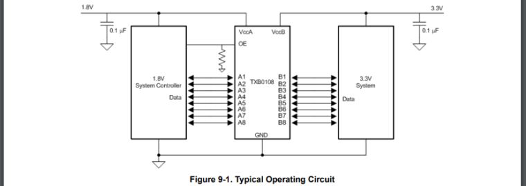
What I did is add Logic Level Converter module between USB to TTL converter and SIM7020G module.
NOTE: Refer datasheet of IC and do the same connection as shown in datasheet for less garbage data and proper communication.
Thank you so much Felix for your help and efforts.

-
Hello @jeetS
you are welcome. I am glad to hear you got it working to your liking. And thank you for letting me/us know and for the detailed step by step explanation.
Thanks
Felix