Revealing the Potential of myCobotM5Stack AI Kit Vision Algorithms
-
Introduction
In this article, we will delve deeper into understanding how the machine recognition algorithm of myCobot 320 AI Kit is implemented. In today's society, with the continuous development of artificial intelligence technology, the application of robotic arms is becoming increasingly widespread. As a robot that can simulate human arm movements, the robotic arm has a series of advantages such as efficiency, precision, flexibility, and safety. In industrial, logistics, medical, agricultural and other fields, robotic arms have become an essential part of many automated production lines and systems. For example, in scenes such as automated assembly on factory production lines, cargo handling in warehouse logistics, auxiliary operations in medical surgery, and planting and harvesting in agricultural production, robotic arms can play its unique role. This article will focus on introducing the application of robotic arms combined with vision recognition technology in the myCobot 320 AI Kit scene, and exploring the advantages and future development trends of robotic arm vision control technology.
Product
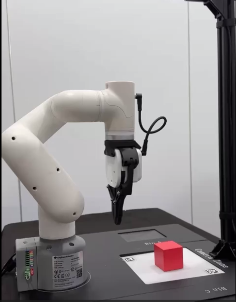
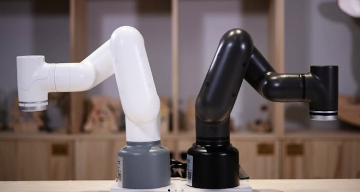
myCobot 320 M5Stack
myCobot 320 is a 6-axis collaborative robot designed for user-independent programming and development. With a motion radius of 350mm, it can support a maximum end load of 1000g with a repetitive positioning accuracy of 0.5mm. It provides a fully open software control interface that enables users to quickly control the robotic arm using a variety of mainstream programming languages.The robotic arm uses M5Stack-Basic as the embedded control board, and ATOM as the core control center of the robotic arm.
myCobot Adaptive gripper
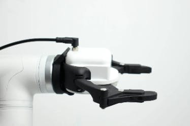
The myCobot adaptive gripper is an end-of-arm actuator used for grasping and transporting objects of various shapes and sizes. It has high flexibility and adaptability and can automatically adjust its gripping force and position based on the shape and size of different objects. It can be combined with machine vision to adjust the gripping force and position of the gripper by obtaining information from vision algorithms. The gripper can handle objects up to 1kg and has a maximum grip distance of 90mm. It is powered by electricity and is very convenient to use. This is the equipment we are using, along with the myCobot 320 AI Kit that we will be using later.Vision algorithm
Vision algorithm is a method of analyzing and understanding images and videos using computer image processing techniques. It mainly includes several aspects such as image preprocessing, feature extraction, object detection, and pose estimation.
Image preprocessing:
Image preprocessing is the process of processing the original image to make it more suitable for subsequent analysis and processing. Commonly used algorithms include image denoising algorithms, image enhancement algorithms, and image segmentation algorithms.
Feature point extraction:
Feature extraction is the process of extracting key features from the image for further analysis and processing. Common algorithms include SIFT algorithm, SURF algorithm, ORB algorithm, HOG algorithm, LBP algorithm, etc.
Object detection:
Object detection is the process of finding a specific object or target in an image. Commonly used algorithms include Haar feature classifier, HOG feature + SVM classifier, Faster R-CNN, YOLO.
Pose estimation:
Pose estimation is the process of estimating the pose of an object by identifying its position, angle, and other information. Common algorithms include PnP algorithm, EPnP algorithm, Iterative Closest Point algorithm (ICP), etc.Example
Color recognition algorithm
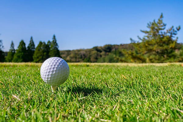
The verbiage is too abstract. Let us demonstrate this step through practical application. How can we detect the white golf ball in the image below? We shall employ the use of OpenCV's machine vision library.
Image processing:Initially, we must preprocess the image to enable the computer to swiftly locate the target object. This step involves converting the image to grayscale.
A grayscale image is a method of converting a colored image to a black and white image. It depicts the brightness or gray level of each pixel in the image. In a grayscale image, the value of each pixel represents its brightness, typically ranging from 0 to 255, where 0 represents black and 255 represents white. The intermediate values represent varying degrees of grayness.
import cv2
import numpy as np

image = cv2.imread('ball.jpg')
# turn to gray pic
gray = cv2.cvtColor(image, cv2.COLOR_BGR2GRAY)

cv2.imshow('gray', gray)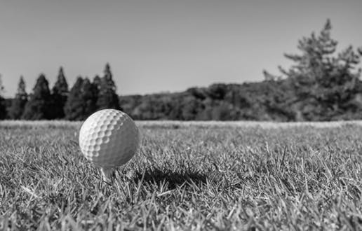
Binarization:As we can observe, there is a significant color contrast between the golf ball and the background in the image. We can detect the target object through color detection. Although the golf ball is primarily white, there are some gray shadow areas caused by lighting. Therefore, while setting the pixels of the grayscale image, we must consider the gray areas as well.
lower_white = np.array([180, 180, 180])  # Lower limit
upper_white = np.array([255, 255, 255])  # Upper limit

# find target object
mask = cv2.inRange(image, lower_white, upper_white)
contours, _ = cv2.findContours(mask, cv2.RETR_EXTERNAL, cv2.CHAIN_APPROX_SIMPLE)
This step is called binarization, which separates the target object from the background.
Contour filtering:
After binarization, we need to establish a filter for the contour area size. If we fail to set this filter, we may encounter the result depicted in the image below, where many areas are selected, whereas we only desire the largest one. By filtering out small regions, we can achieve our desired outcome.
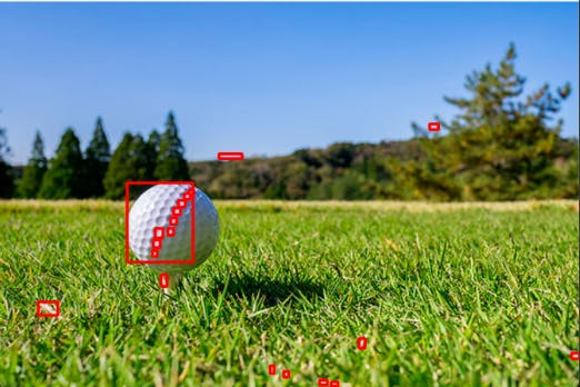
#filter
min_area = 100
filtered_contours = [cnt for cnt in contours if cv2.contourArea(cnt) > min_area]

#draw border
for cnt in filtered_contours:
    x, y, w, h = cv2.boundingRect(cnt)
    cv2.rectangle(image, (x, y), (x+w, y+h), (0, 0, 255), 2)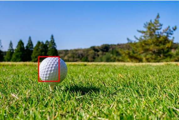
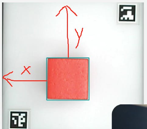
import cv2
import numpy as np

image = cv2.imread('ball.jpg')
gray = cv2.cvtColor(image, cv2.COLOR_BGR2GRAY)

lower_white = np.array([170, 170, 170])
upper_white = np.array([255, 255, 255])

mask = cv2.inRange(image, lower_white, upper_white)
contours, _ = cv2.findContours(mask, cv2.RETR_EXTERNAL, cv2.CHAIN_APPROX_SIMPLE)
min_area = 500
filtered_contours = [cnt for cnt in contours if cv2.contourArea(cnt) > min_area]

for cnt in filtered_contours:
    x, y, w, h = cv2.boundingRect(cnt)
    cv2.rectangle(image, (x, y), (x+w, y+h), (0, 0, 255), 2)


cv2.imshow('Object Detection', image)
cv2.waitKey(0)
cv2.destroyAllWindows()
It is important to note that we are utilizing a robotic arm to grasp the object. Hence, merely detecting the target object is insufficient. We must obtain the coordinate information of the object. To achieve this, we use OpenCV's Aruco markers, which are commonly used 2D barcodes for tasks such as camera calibration, pose estimation, and camera tracking in computer vision. Each Aruco marker has a unique identifier. By detecting and recognizing these markers, we can infer the position of the camera and the relationship between the camera and the markers.
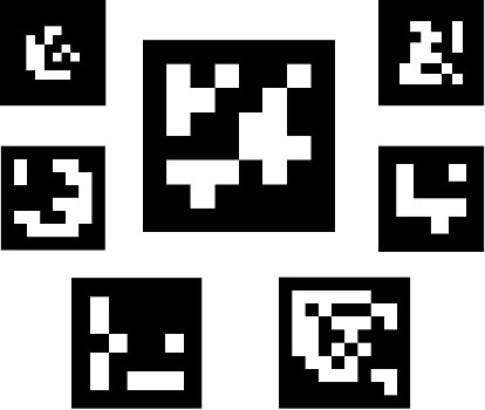
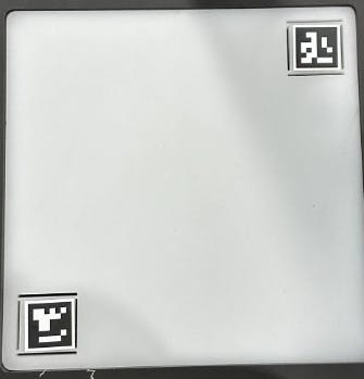
The two unique Arcuo codes in the picture are used to fix the size of the cropped picture and the position of the arcuo code, and the target object can be obtained through calculation.
With the Aruco marker's positioning, we can detect the location of the target object. We can then convert the x and y coordinates into world coordinates and provide them to the robotic arm's coordinate system. The robotic arm can then proceed with grasping the object.

# get points of two aruco
 def get_calculate_params(self, img):
        """
        Get the center coordinates of two ArUco codes in the image
        :param img: Image, in color image format.
        :return: If two ArUco codes are detected, returns the coordinates of the centers of the two codes; otherwise returns None.
        """
        # Convert the image to a gray image
        gray = cv2.cvtColor(img, cv2.COLOR_BGR2GRAY)
        # Detect ArUco marker.
        corners, ids, rejectImaPoint = cv2.aruco.detectMarkers(
            gray, self.aruco_dict, parameters=self.aruco_params
        )

        """
        Two Arucos must be present in the picture and in the same order.
        There are two Arucos in the Corners, and each aruco contains the pixels of its four corners.
        Determine the center of the aruco by the four corners of the aruco.
        """
        if len(corners) > 0:
            if ids is not None:
                if len(corners) <= 1 or ids[0] == 1:
                    return None
                x1 = x2 = y1 = y2 = 0
                point_11, point_21, point_31, point_41 = corners[0][0]
                x1, y1 = int((point_11[0] + point_21[0] + point_31[0] + point_41[0]) / 4.0), int(
                    (point_11[1] + point_21[1] + point_31[1] + point_41[1]) / 4.0)
                point_1, point_2, point_3, point_4 = corners[1][0]
                x2, y2 = int((point_1[0] + point_2[0] + point_3[0] + point_4[0]) / 4.0), int(
                    (point_1[1] + point_2[1] + point_3[1] + point_4[1]) / 4.0)

                return x1, x2, y1, y2
        return None

    # set camera clipping parameters
    def set_cut_params(self, x1, y1, x2, y2):
        self.x1 = int(x1)
        self.y1 = int(y1)
        self.x2 = int(x2)
        self.y2 = int(y2)

    # set parameters to calculate the coords between cube and mycobot320
    def set_params(self, c_x, c_y, ratio):
        self.c_x = c_x
        self.c_y = c_y
        self.ratio = 320.0 / ratio

    # calculate the coords between cube and mycobot320
    def get_position(self, x, y):
        return ((y - self.c_y) * self.ratio + self.camera_x), ((x - self.c_x) * self.ratio + self.camera_y)
Summary
Vision-based control technology for robotic arms is a rapidly developing and widely applied technology. Compared to traditional robotic arm control technology, vision-based control technology boasts advantages such as high efficiency, precision, and flexibility, and can be extensively utilized in industrial production, manufacturing, logistics, and other fields. With the constant evolution of technology such as artificial intelligence and machine learning, vision-based control technology for robotic arms will have even wider application scenarios. In the future, it will be necessary to strengthen technological research and development and innovation, constantly improving the level of technology and application capabilities.
Hello! It looks like you're interested in this conversation, but you don't have an account yet.
Getting fed up of having to scroll through the same posts each visit? When you register for an account, you'll always come back to exactly where you were before, and choose to be notified of new replies (either via email, or push notification). You'll also be able to save bookmarks and upvote posts to show your appreciation to other community members.
With your input, this post could be even better 💗
Register Login