Power Supply of COM.LTE (SIM7600)
-
Hi @felmue
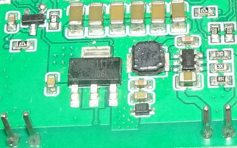
That's it: AMS1117. The 33 is written on the second line, on the left under the dirt.
Regards, Dan
-
There is 0ohm between the adjust pin of the AMS1117 and the GND pins of the board.
-
Hello @DanK
interesting. My COM.LTE board looks like this one.
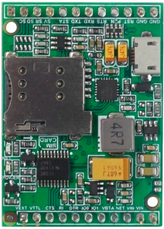
No AMS1117 on that board.
Thanks
Felix -
Hello @felmue
well, what can I say but: That's weird.Now, just look at M5's pictures of the module. On their doc site, it's yours. On the shop site, it's mine...
I think we get to the core of the problem. I just measured the voltage, when USB is connected on the M5stack Core Basic 2.7, at the input of ther regulator: 4.3V ! At its output it has 2.8V. That's way off the 3.4V limit.
So the issue is not so much the type of regulator, but the question whether or not we can use internal power supply or not. My understanding of M5's specification is that external power supply is explicitly needed only with Core 2 and Fire. If that wasn't the case, why connect the M-Bus voltage to the module at all.
It seems to be clear now, that power supply MUST be external.
@M5 : Please comment, thanks!
-
@dank said in Power Supply of COM.LTE (SIM7600):
. On the shop site, it's mine...
Do you have a link to the shop site that shows the board that looks like yours?
-
Link shop: https://shop.m5stack.com/products/com-lte-modulesim7600g
Link doc: https://docs.m5stack.com/en/module/comx_lteWorse: They not even changed product code. Both have product no: M031-A.
The first item I bought was the one on the doc site, the one that felmue showed. That worked fine. First customer happy. Then I bought 10 new ones, without being told it's another board inside. Now customers are very unsattisfied. Me too.
-
Hello @DanK
well, there is another difference. The one I have is a SIM7600G (which is only CAT1) whereas it seems the shop now sells SIM7600G -H. The H actually makes it a CAT4 device (as advertised). See my post here.
BTW: mine had very poor reception until I realized the antenna cable was connected to the GPS connector by mistake. My post at the time.
Thanks
Felix -
Hi @M5,
One more attempt to appeal to your sense of responsibility. I powered the SIM7600G-H Module with 5.0V, between Vin and GND. I measured the following voltages between the pins of the AMS1117 voltage regulator and GND:
1: (GND/Adjust): 0.0V
2: Vin: 3.75V
3: Vout: 2.85VIf the SIM7600 modem is connected to the output of the regulator, which is assumed, then the minimum operating voltage is significantly undershot.
Please respond to these findings and publish a diagram of the green piggyback circuit with the SIM7600 modem. Of particular interest is the connection between Vin and the input of the regulator. Why aren't the 5.0V input voltage making it to the input of the regulator?
Thanks and kind regards,
Dan -
Hello @DanK
looking at the picture you've posted again I don't think the AMS1117 is the regulator for the SIM7600G-H. I think the 6 pin IC labelled JB3N (or so) on the right side is - the traces from Vin also go there. The output of that IC goes through the coil (squarish black thing) which is then feed into the AMS1117 pin 3. So my guess is that the SIM7600G-H is actually powered from the 3.75 V coming out of the coil. This would almost match the recommended voltage of 3.8 V.
Note: I am obviously guessing here as I do not have this particular green board to verify myself.
While we do not have the schematic of the green board we do have the pinout of the SIM7600G-H so you could double-check (if you haven't already) what the actual voltage is that goes into VBAT (pin 38, 39, 62, 63).
Note: if my above assumptions are correct then I don't know what the AMS1117 is doing and what it's output voltage is needed for. Well, maybe it's used for the active GPS antenna.
Thanks
Felix -
Hi @felmue
you are perfectly right! The SIM7600G-H is not powered by the AMS1117. It's actually the regulator's input voltage that also goes to the Vbat of the SIM modem (Pins 62 and 63).
It's good to know the SIM modem is powered correctly.
But: what ever the AMS1117 does, it's NOT used correctly.
Thanks again for your help!
Kind regards, Dan -
Hello @DanK
actually there is an AMS1117 version with exactly the output voltage you measured: 2.85 V - coincidence?
From the AMS1117 datasheet - feature list: Three Terminal Adjustable or Fixed Voltages* 1.5V, 1.8V, 2.5V, 2.85V, 3.3V and 5.0V
But yes, the input voltage is probably on the low side.
Thanks
Felix
Hello! It looks like you're interested in this conversation, but you don't have an account yet.
Getting fed up of having to scroll through the same posts each visit? When you register for an account, you'll always come back to exactly where you were before, and choose to be notified of new replies (either via email, or push notification). You'll also be able to save bookmarks and upvote posts to show your appreciation to other community members.
With your input, this post could be even better 💗
Register Login