M5 Tough UART Communication
-
I have a Distance Sensor V-LD1 and try to read Sensor data in M5 Tough through UART pins 13/14(RX/TX). But communication between M5Tough and Sensor isn't working properly.
-
-
Hello @felmue ,
No, I'm not using any level shifter. I'm simply connecting the UART Port-C (Blue) of my M5 Tough with the sensor.
-
@alee35 if the sensor uses 1.8V logic for its UART and the Tough uses 3.3V you may need a level shifter as you may risk killing the sensor from the toughs 3.3V
-
@ajb2k3

Please find the attached image for your reference. I'm using the Eval Kit of the VLD-1 Sensor, which requires a power supply of 5V. I suspect there might be an issue with the UART, as I am unable to read data on the Serial Terminal when connecting my sensor to the M5Tough UART Port-C (Blue). I have a feeling that perhaps their UART isn't receiving power or there's something wrong with it -
Hello @Alee35
hmm, looking at the datasheet for the eval board I cannot find any info about the voltage RX and TX are using. That said, my best guess is that since it is meant for the FTDI cable and the power supply requires 5 V you would still need a level shifter from 5 V of the eval board to the 3.3 V of the M5Tough.
With only GND and 5 V supplied to the eval board you should be able to measure the voltage of the TX pin. If it is different from 3.3 V you'll need a level shifter.
Note: the M5Tough supplies 5 V on the groove connector, but the RX and TX lines are only 3.3 V as they are coming directly from the ESP32.
Thanks
Felix -
@felmue I am @Alee35's colleague. I connected the Vcc(5VDC) and the Gnd pins only and measured the voltage on the TX and RX pins of the VLD-1 Eval board. On Tx pin there is no voltage, but on the RX pin i am getting 3.3V. Is it becuase the sensor waits for the INIT command before transmitting the data on UART? In any case i switched the wiring and the sensor is still non responsive. I double checked for loose wiring and for any other wiring issues but everything seems to be in order. I tested the sensor again by connecting it to serial terminal and it is giving correct output. I also checked the voltage on pin 13 and 14 of M5, pin 13 which is RX has 0 V and pin 14 which is Tx has 3.3V. We tested with ESP32 programming via PlatformIO with multiple permutations and combinations on serial ports, pin nos etc, but nothing seems to work. I also programmed another new M5Tough with UiFlow but the result is same. See below a screenshot of the UIFlow code in Python. We are completely stuck and are surprised that such a simple thing isnt working. Pls advise if you can think of something which might help.
import os, sys, io
import M5
from M5 import *
from hardware import *label0 = None
#uart2 = Nonedef setup():
global label0, uart2uart2 = UART(2, baudrate=115200, bits=8, parity=None, stop=1, tx=9, rx=10, rts=-1, cts=-1, txbuf=256, rxbuf=256, timeout=0, timeout_char=0, invert=0, flow=0)
M5.begin()
Widgets.fillScreen(0x222222)
label0 = Widgets.Label("Text", 152, 96, 1.0, 0xffffff, 0x222222, Widgets.FONTS.DejaVu18)uart2.init(baudrate=115200, bits=8, parity=0, stop=1, tx=32, rx=33, rts=-1, cts=-1, txbuf=256, rxbuf=256, timeout=0, timeout_char=0, invert=0, flow=0)
uart2.write('I')
uart2.write('N')
uart2.write('I')
uart2.write('T')
if uart2.read(1):
label0.setText(str(uart2.read(10)))def loop():
global label0, uart2
passif name == 'main':
try:
setup()
while True:
loop()
except (Exception, KeyboardInterrupt) as e:
try:
from utility import print_error_msg
print_error_msg(e)
except ImportError:
print("please update to latest firmware")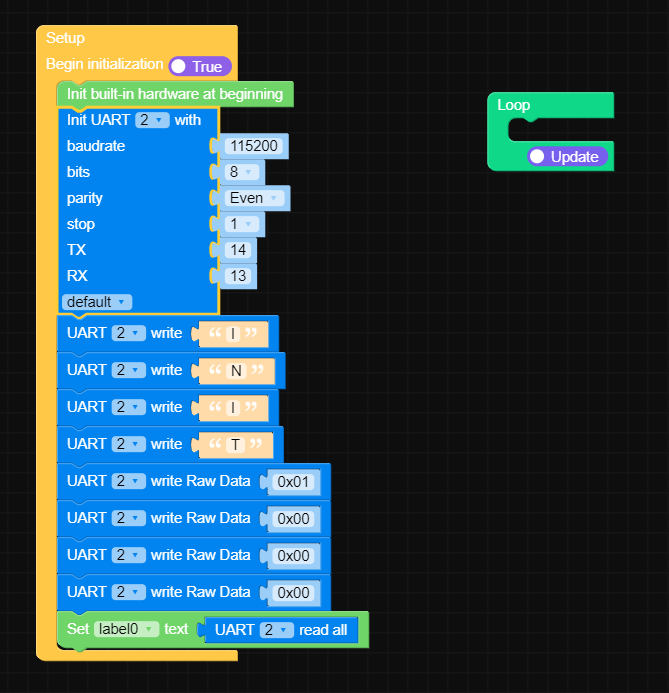
-
Hello @samkhan2050
it is hard to tell what is going on as I do not have this sensor and I cannot test myself.
Yes, I think it is possible that the sensor is waiting for the INIT command before doing / sending anything.
I also noticed that the Micropython code you posted doesn't seem to match the posted UIFlow blocks. In the Micropython code I can see two UART init lines, both not using the correct RX and TX pins.
uart2 = UART(2, baudrate=115200, bits=8, parity=None, stop=1, tx=9, rx=10, rts=-1, cts=-1, txbuf=256, rxbuf=256, timeout=0, timeout_char=0, invert=0, flow=0)

uart2.init(baudrate=115200, bits=8, parity=0, stop=1, tx=32, rx=33, rts=-1, cts=-1, txbuf=256, rxbuf=256, timeout=0, timeout_char=0, invert=0, flow=0)
Thanks
Felix -
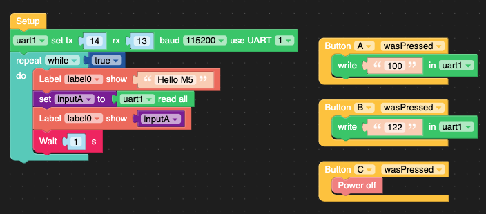
@samkhan2050, In case it helps, I connected my Core2 to a micro:bit using the following sketch in UIFlow and UART. Assuming the pins of the M5Tough are the same/similar, could you connect only the transmit wire of the eval board to the receive pin of the M5Tough (maybe with a common GND). I would expect that the trigger from PC could still be sent and monitored on the rx of the M5Tough. Likewise, if you have another M5 you could test M5-to-M5 to baseline the pins, etc.
-
@felmue and @gavin67890. Thanks for trying to help us out. I am glad to inform that the serial communication worked. Somehow, its not Serial2, but Serial1 which is UART at pin 13 and 14 of M5Tough. Additionally, M5Tough.h library didnt work, we had to use M5Unified. Everything is working fine now except, one issue. Till now we were running the M5Tough using the USB cable. FOr it to be used in our application, we need to provide it with 24DC power supply. In order to enable 24VDC power supply input for M5Tough, we need to add the following code in the setup:
auto cfg = M5.config();
// MBus power input
cfg.output_power = false;
M5.begin(cfg);The issue is that when i do that my UART connection stops working. It seems as if cfg.output_power = false disables the UART port or something. What could be the possible reason? Any guesses?
-
Hi @samkhan2050, Err, possibly. Any reason that line can't just be omitted in your code (leave as default, which is true) or change it to "... = true;"? I'm unclear why it would affect the 24 VDC input – I run my Core2s on bases this way with sensors attached, which run off the 5 VDC.
-
@gavin67890 In M5Tough, there is an external board called M5Tough EXT board in which we connect the 24VDC supply. This 24VDC supply is then converted to 5VDC and then it goes to ESP32 through the 5VDC pin on the main board. If i dont make the output_power = false, then the 5VDC pin stays high on the main board and also on the EXT board (from external supply) which does not allow ESP32 to switch on. So if we make it false, then the main board 5VDC output becomes low and then it can be driven by the external supply from the M5 Tough EXT board. This is the only way to power up the M5Tough using 24VDC supply. I am not sure about core2 though. Now i figured that in this scenario, the UART doesnt get disabled. It keeps working, but the sensor communication doesnt work. To my surprise, if i disconnect the sensor while the power is on and reconnect it, the sensor start communicating. I feel that somehow, ESP32 doesnt like that the sensor is powered up before the ESP32 is initialized as both the sensor and ESP32 are getting powered by the same external 5VDC supply. Now the only option for me is to setup a GPIO pin to drive a mosfet which would then power up the Sensor after ESP32 is initialized. But i feel there must be a much simpler way to do this via programming.
-
When I'm running certain GPIO pins by adding a 24V supply and driving a transistor (TIP41C) to activate the relay, it works fine as long as the relay doesn't drive any power. However, the moment the normally open (NO) contact of the relay drives power, after some time, the touchscreen of M5Tough stops working, and the screen displays fully black
Hello! It looks like you're interested in this conversation, but you don't have an account yet.
Getting fed up of having to scroll through the same posts each visit? When you register for an account, you'll always come back to exactly where you were before, and choose to be notified of new replies (either via email, or push notification). You'll also be able to save bookmarks and upvote posts to show your appreciation to other community members.
With your input, this post could be even better 💗
Register Login