Help with AIN4-20mA units
-
Hello
I have two single channel AIN4-20ma units for a logging project. I am struggling to get them to work due to a combination of poor knowledge and documentation. I have the units connected to an ESP32 and I can see and read data from them but i do not know how to connect the 4-20ma signals. I have set the jumper to external 24V supply and have connected 24v to GND and 24V I only have a 4-20Ma tester and DFrobot 4-20Ma DAC all my attempts to connect these to the AIN4 give only a zero
I am sure it is me can anybody help with a simple circiut diagram for me to test
Couple of things i am running the module on 3.3V is that ok? and for the single channel unit the channel to use will be 0?
Thanks in advance -
This one?
https://shop.m5stack.com/products/ain4-20ma-unitand you mean "external" as like so?
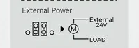
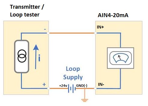
Then you should not use the 24V and GND only IN+ and IN- like so and wtih your Transmitter/tester in "passive" mode (may need to read the manual of you tester):
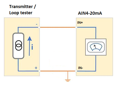
if your transmitter/tester is "active" then you should connect like this - i.e. no need for a separate power supply:
-
Thank you very much i begin to see how to coonect the modules connecting in active mode seems to work with the tester
Thanks again -
Further to my post. I have two modules working on an ESp32 but i need to get them working on a ESP8266. I know the libraries have been written with ESP32 in mind
I have got the code to compile for ESp8266 but when loaded it return only 255 or 65535 for the ADC values or i2c address
Can anyone advise on what changes to make to the libraries
Thanks
Hello! It looks like you're interested in this conversation, but you don't have an account yet.
Getting fed up of having to scroll through the same posts each visit? When you register for an account, you'll always come back to exactly where you were before, and choose to be notified of new replies (either via email, or push notification). You'll also be able to save bookmarks and upvote posts to show your appreciation to other community members.
With your input, this post could be even better 💗
Register Login