Controlling a PPS module with an STM32 Nucleo board instead of an M5 Core controller
-
Hi,
I'm new to the M5 platform, but I've got a project where the M5Stack PPS power supply module looks like a pretty good fit for the features we want -- it's a nicely-packaged little programmable 5V power supply. The trick is that the rest of our embedded device stack is built around an STM32 Nucleo-H723ZG dev board, so I'm hoping I can talk to the PPS module via I2C directly instead of using an M5 Core controller.
I've had partial luck attempting this by porting the M5Module-PPS Arduino example code to run on the Nucleo, but I seem to be hitting an odd incompatibility:
I2C communication works during the Arduino
setup()phase, but goes wonky during the mainloop().So that's the central mystery. Some additional details:
During
setup(), I can query values, configure power output parameters, enable/disable the PPS, etc. Once the mainloop()starts, it goes off the rails -- invalid data returns, the PPS sometimes goes into odd modes, and sometimes some IO appears to enter deadlock (e.g. serial print statements stop reporting back to my PlatformIO host)Note that the same PPS module works fine when I deploy the functionally-identical example code to my M5 Core3 SE controller. So there's clearly some difference between how my STM32 Nucleo is interfacing to it vs how the M5 controller is.
My only real hypothesis thus far has been that I misunderstood the wiring or voltage assumptions (e.g. 3.3V vs 5V), but I think I've verified that is correct (though, I'll admit, I find M5's docs and schematics a bit inconsistent and hard to follow). FWIW, I did some basic probing of the M5 Core3 SE and confirmed that it's I2C pins appear to operate on 3.3V, so that's my working assumption.
What I have wired up now:
- PPS I2C pins on the M5Bus header: SCL/SDA pins (as identified on PPS page linked above) connected directly to the STM32's I2C_B interface pins. For reference, these same header pins correspond to the Core3 SE's GPIO11/12 pins AKA intSCL/intSDA on the controller.
- PPS GND tied to Nucleo GND
- PPS 3V3 pin tied to Nucleo's 3V3 plane
Anyone see something obvious I missed? Or are there some other aspects of interfacing to this thing that I just haven't understood?
-
Hello @foofera
hmm, the I2C communication working in
setup()suggest the wiring is ok.Are you using pull-up resistors on
intSCLandintSDA?Have you tried lowering the I2C bus speed?
Have you tried to put a delay between issuing I2C commands in your
loop()code?Have you tried to control a different I2C slave device from your STM32? Does that work in both
setup()andloop()?Thanks
Felix -
It sounds like your I2C works during setup but fails in the loop, which may indicate timing or bus handling issues on the STM32. Make sure you’re properly handling I2C interrupts and not blocking the bus in your main loop. Also, check that your I2C clock speed matches what the PPS module supports. STM32’s HAL I2C functions sometimes behave differently from Arduino’s Wire library, so review how you manage repeated start conditions and error handling. Double-check pull-up resistors on the I2C lines and confirm the voltage levels are stable at 3.3V during runtime.
-
Thanks for the quick and thoughtful replies, @felmue and @hacxx.
First, just to clarify a specific point: can we say authoritatively that the M5 + PPS module are designed to communicate natively using 3.3V I2C? I've seen other forum/reddit posts that seem a bit inconsistent about the 3.3V vs. 5V question, and that remains a basic spec that I have yet to find an authoritative clear answer about in M5's official docs.
To answer some of your questions and theorize a bit further:
-
Yes, I've got the STM32 communicating with another I2C device; specifically, a DS2484 module which translates to OneWire protocol. That can reliably round-trip all the way down to my 1W EEPROM, so no reason to suspect fundamental issues with I2C on this board. More thoughts on that below.
-
Pull-ups: I have not added my own pull-ups here because I'm using pins on the STM32 that are designated for I2C usage (PF0 + PF1, AKA I2C_B), and my reading of the ST docs is that they already have appropriate pull-ups.
-
I2C speed: I have tried both the 400kHz speed that the M5 example uses and taken it down to 100kHz. I haven't looked at the speed question beyond that. AFAIK, the PPS module supports both (and regardless, I'm pretty sure I tested both while deploying to the M5 Core3 SE).
-
I have tried some different delays in between commands, with no particular impact that I can see.
Regarding the other I2C device: I should be clear that I've been using different I2C pins for this (i.e. a different logical I2C bus on the STM32), but only on a "why not?" kind of basis because we only expect this whole assembly to ever use 2 I2C devices so figured might as well isolate them. I mention this bit simply because it means I have not verified I2C with another downstream device over exactly the same STM32 pins.
Regarding other potential factors: I did eventually observe that removing some/all of my
Serial.println()statements from theloop()body seemed to make things incrementally happier. That is one of the clues pointing toward the general class of issues @hacxx refers to, e.g. perhaps some timing/bus-contention subtleties in the STM32 / Arduino stack implementation? My deeper embedded debug skills for that sort of thing are bit rusty, but I'm curious if y'all have any further thoughts on the value of poking deeper and/or any suggested methodologies/tools to do so?Finally, to touch on @hacxx's point regarding differences between STM32's HAL vs. Arduino: I've been building my prototypes on the Arduino stack thus far mostly out of sheer convenience (and in the case of the M5 demo code, so I could do an otherwise apples-to-apples compare between the MCU targets). I've been considering porting over to STM32Cube or maybe some other middleware stack if it has significant advantages. I'm curious if y'all have any further thoughts on that?
-
-
Oh, one more question from the "dumb questions about I2C" department... Could I plausibly run I2C to the PPS at an otherwise ridiculously low clock rate and expect it to work? i.e. is it a valid troubleshooting technique to set the I2C rate down to something like 1 kHz (or even lower) to see if that dodges some timing sensitivity? The components involved definitely ought to be capable of much higher bit rates, but as it turns out I never expect to actually exchange more than a few dozen bytes with this thing under real conditions -- its programming protocol is extremely simple. So communicating at a very low bit rate is definitely acceptable from a pure functionality perspective.
-
Found a little more time to troubleshoot this with the actual hardware today as well as squint at the datasheets again.
I was at least able to determine a couple more things:
-
I believe I've finally understood the schematics well enough to confirm that the M5 PPS operates on 3V3 I2C. I had previously gotten mixed up while trying to sort out M5's various conventions for labeling the different I2C lines (e.g. prefixes like SYS/ISO/INT/PA) as well as the fact that the M5 PPS schematic is split across two pages and I hadn't understood the precise relationship there.
TL;DR: The pins I'm using are the ISO_SCL/ISO_SCL pins as shown in the schematic below, and they are tied to the VDDB pin on the U1 isolator component, which in turn is powered via ISO_3V3 from the header.
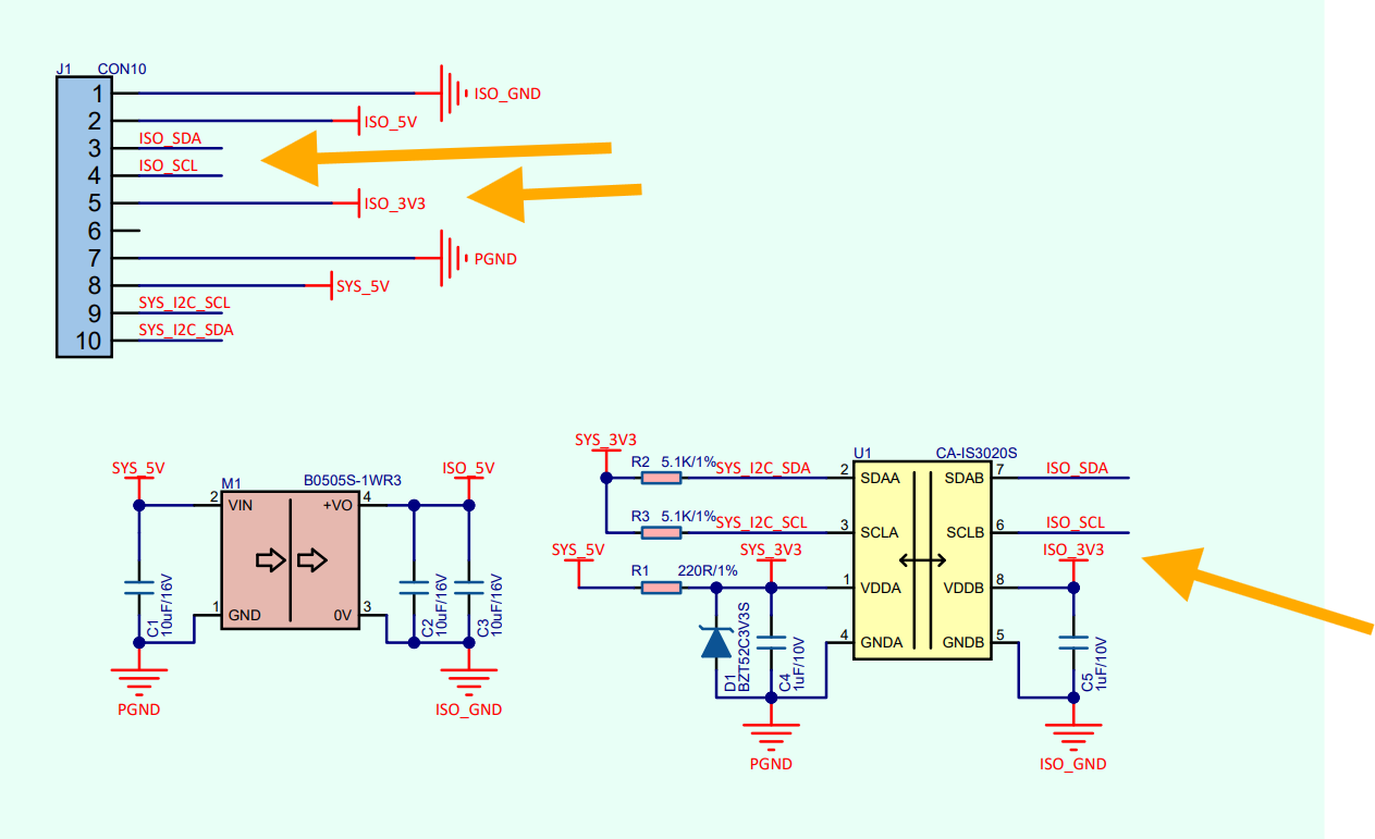
(I also finally understand the "ISO" prefix as meaning "isolated plane", which, OK, I'll admit to a little facepalm that this wasn't obvious to me earlier.)
My wiring to the STM32 Nucleo ties ISO_SCL/ISO_SDA directly to corresponding pins on the Nucleo, while sourcing ISO_3V3 from the STM32's IOREF pin (and FWIW, I've also tried the STM32's dedicated 3V3 pin as well as probed those pins to confirm 3.3V that looks stable).
-
Just because it was easy to test, I tried adjusting the I2C speed parameter wayyyyy down to the comically-slow 1 kHz -- with no apparent change in behavior... but then the moment I wrote that, I realized I should check whether the Adruino
TwoWireimplementation I'm using actually supports arbitrary speed. Sure enough, it coerces ALL speed parameter values to one of the de facto standard values of[100 kHz, 400 kHz, 1 Mhz]. So... apparently I proved nothing via that test and doing otherwise would require hacks I'd rather not get into unless that's a pretty strong hypothesis. Sigh.
-
-
@foofera I don't know if you ever progressed this issue, but I suggest you try adding a 100us delay between API calls to the PPS library.
I suggest this because I've found the example code unreliable with a core2, with periodic lockups showing Nack errors on the core2. Very sensitive to host app timing. I think the firmware sometimes goes into error handling and the restart logic is too slow for quick subsequent calls to succeed.
With stock code, I find the example app hangs after a few seconds to a few minutes. I've tweaked the library to check the gap between the end of one call and the start next, and if under 100us it adds delayMicroseconds() to extend gap to 100us. It now runs for days without issue.
I think the real fix is to also improve the library error handling with retries, but the delay fix works for my use case.
-
@colintd I appreciate the follow-up, as I had been meaning to post back here as well.
Happily (for me), it's no longer getting in my way since I did ultimately decide to port my project to using STM32Cube HAL API instead of Arduino Wire APIs. After that, I've had zero such issues.
I realize that doesn't help folks much who are stuck using Arduino APIs for whatever reasons (or prefer those APIs -- there are some advantages).
Your theory is interesting, though. I honestly don't remember how deeply I looked into inter-call delays and/or deeper status checking at the time. I could believe that perhaps the Arduino Wire API implementations on different hardware could also lead to subtle timing differences... and if it is also specific to the M5 PPS device, those docs aren't ultra-specific about what the device actually expects w.r.t. delays, etc.
TL;DR: It was an interesting side quest, which I ultimately solved by changing middlewares. ╰(°▽°)╯
Hello! It looks like you're interested in this conversation, but you don't have an account yet.
Getting fed up of having to scroll through the same posts each visit? When you register for an account, you'll always come back to exactly where you were before, and choose to be notified of new replies (either via email, or push notification). You'll also be able to save bookmarks and upvote posts to show your appreciation to other community members.
With your input, this post could be even better 💗
Register Login