M5Paper EPD power consumption
-
-
Hello @felmue
Thanks for showing the start point of the search. (I go to Github to see the realization of this function and also to see how here working with RTC alarm, gotten PINs, and schematic becomes 100 times clear for me) I can answer my question myself.
At normal POWER_OFF state - PWR_EN point in schematic setted to HIGH (VBAT_IN -> R35 -> D10 - >C94), it,s HIGH state block power from VBAT_IN -> VBAT use FET1 to close this path.
When we push button(and hold it for some seconds) we open path PWR_EN ->D10 -> KEY_PUSH -> GND, which set PWR_EN to LOW and open path VBAT_IN -> FET1 -> VBAT. VBAT powered chain of DC, and power our ESP32. After start ESP32 push the virtual button(FET2) using PS_ON, which opens path PWR_EN->FET2->GND, and stable hold power to DC(and sensors and esp32), and now we can realese push button, and all will still work.
When we set ALARM to RTC PCF8563, and then release FET2, we allow to PWR_EN become HIGH again through 100k resistor R35. When it becomes HIGH, it automatically powers off our ESP32, DC-DC, and sensors. But RTC PCF8563 will still work cause it powered over VBAT_IN.
When alarm time becomes - PWR_EN setted low through path PWR_EN -> D7 -> RTC_ALARM - >INT - > GND. Which allow ESP32 to start again.
Thanks!
-
Yes, it's pretty straight forward to power down the ESP32 completely and the power draw in that state is about 1.5 uA.
I did play around more with power down states and I managed to get a light sleep mode with fast wakeup from touch at around ~9mA.
I didn't get to play around with doze mode yet. I hope to get 1-2 mA when touch is in doze (gesture?) mode and ESP32 in deep sleep.
-
Hello @tatar-andrei,
I am also going to use a power supply to continue analyzing the consumption of the various components because IT consumes a lot.
Can we turn it off with a mos then turn it on again?
Will it be able to reset itself without the ESP32 sending it an initialization sequence?
I will study this ...
SYL -
@tatar-andrei said in M5Paper EPD power consumption:
1.5 uA.
@tatar-andrei could ou please share how you managed to get down to 1.5 uA? Is the ESP32 still in deepsleep in this state and can be woken up via RTC/timer or is the unit completley turned off and needs some user-interaction in order to wake up?
(I have no M5paper yet and want to find out if it is suitable for my project).I am highly interested in how much amperage is drawn in deepsleep with the RTC configured to wake the ESP32 up in regular intervals. Could you please test this? Thanks man!
-
could you please share how you managed to get down to 1.5 uA?
Turn off the mosfet that powers the ESP32 (
M5.disableMainPower();- https://github.com/m5stack/M5EPD/blob/main/src/M5EPD.h#L49). In this mode everything but the external RTC (BM8563) is powered off.In order to wake up from this mode you either need to press the button on the side, or use the external RTC interrupt.
The M5 lib contains a few functions that do exactly this (setup the external RTC to wakeup the board in a few seconds): https://github.com/m5stack/M5EPD/blob/main/src/M5EPD.cpp#L133 -
Hello @tatar-andrei,
With a supply of 4.2V, U(R35)=11mV, equivalent to 1.1µA for RTC and zener D11current.
Equivalence names table
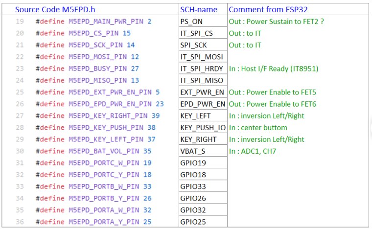
There is inversion between Left and Right, why not having simply called the buttons Top and Bottom?
SYL
-
Hello,
i also made a fisrst compact schema to facilitate understanding
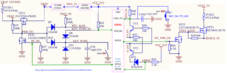
SYL
-
Hello,
If the repository is facing the wheel,
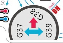
"code source" is true, "SCH-name" is false

SYL
-
Hello,
I completed the schema with VUSB_IN, VSYS and OR fonction with D9,D12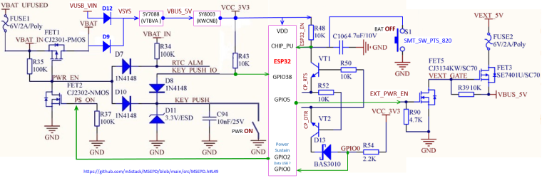
SYL
-
I just received my M5Paper and I can not get a 100% charge? The power consumption also seems high. I am only observing the battery level indicator relative to device use. Is there a problem with the firmware? Is the Wifi function draining the battery prematurely?
-
Hello,
On mine, the maxi level indicator of charge is 86% corresponding to 4.18V
I measured USB current with the program "Factory test" and a serial USB device named "UT25".
The value is 131 mA, without interraction.
I also wrote personal comments about all GPIOs (in french, my native language):
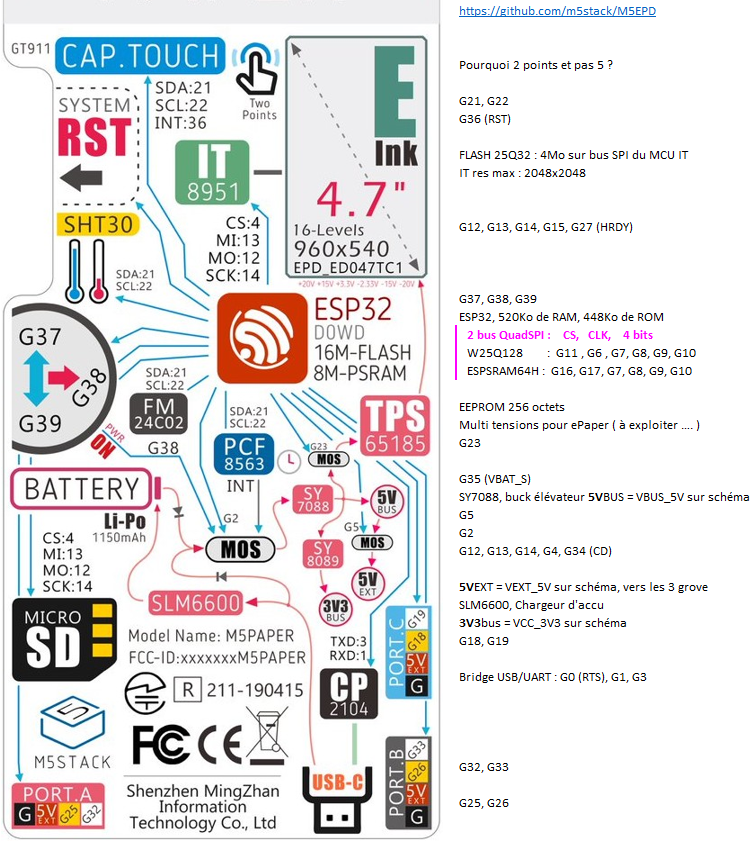
All GPIOs are represented (except non-existent ones : 20, 24, 28, 29, 30, 31)
SYL -
@tatar-andrei
Hello!I was wondering if you could provide some reference for how you got into doze mode/wake on touch? I've been trying for a few days now and for the life of me can't seem to make any meaningful progress.
-
You can check other GT9xx drivers like (http://read.pudn.com/downloads710/sourcecode/embedded/2849392/gt9xx.c__.htm).
I will need to play some more with it. I'll probably post here a link to my repo once I push the code.
-
Hello,
If you want to measure RTC and zener D11 current, i indicate the PCB resistors positions
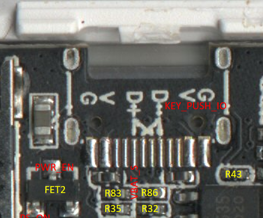
SYL -
Hello,
As I was saying five days ago,
"I measured USB current with the program "Factory test" and a serial USB device named "UT25".
The value is 131 mA, without interraction."
Since then, I have measured the current according to the different programs :
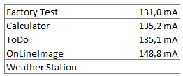
The cause of this excess consumption is IT8951.
An alternative to this component is the 74HC4094D, 8-stage shift-and-store bus register, used as IO extander.
A competitor with the same display consumes 65 mA, i measured to.
SYL -
Hello,
Here is Shift Register schema, the brend is Nexperia.
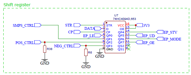
SYL -
@bricox nice work on mapping out the power management system! I've noticed some peculiarities with the charging PMIC (SLM6635, which does not seem to have any english documentation). Specifically, it does not seem to have a proper measuring system set up while charging. Once you connect it to USB power, the indicated battery voltage is actually the charging voltage of the battery, which can be 20-30% higher than the actual (resting) voltage of the battery. This is quite visible if you let the M5Paper with the FactoryTest firmware run out of battery, then connect it to power and head to the factory test screen - the battery indicator will be between 30-50%, and reported battery voltage will be around 3.7-3.8V (which is impossible on a device that was just completely discharged).
The main problem with this is that the battery cutoff voltage for charging seems to be 4.2V - even though the battery is rated 4.35V officially. You can see this, again, on the Factory firmware, by leaving the unit to charge. Once it hits 4.2V stable, charging is cut to that voltage (and the M5Paper displays ~85% battery left). If you disconnect the charger and reconnect it, charging voltage jumps up to 4.35V, however after some time it stops charging (or switches to trickle charging? Not sure about the inner workings of SLM6635), battery voltage slowly drops to 4.2V, and keeps idling there, requiring another disconnect-reconnect to fully charge it again.
I was wondering, since there seems to be some rudimentary control over power management, would it be possible to reset the charging circuit, or somehow fake the disconnect-connect cycle on it? Even if it's a software workaround, it would be nice to be able to properly charge to maximum capacity - and also it would allow to collect appropriate readings while charging.
What I hope for is that the next M5Paper generation gets a better power management solution, even if it's more expensive. Proper PMIC control - especially in low-power applications where one would use an eink screen with an ESP32 for periodic updates - is incredibly important, and right now, by the looks of it, all we have is analog voltage readouts of VBAT, not even the charging/charging complete signals are hooked up (which are arguably important here as well).
Another thing I thought about regarding power saving - would cutting the power to the EXT ports and the EPD display (via methods
disableEPDPower()anddisableEXTPower()) result in any savings?The cause of this excess consumption is IT8951.
An alternative to this component is the 74HC4094D, 8-stage shift-and-store bus register, used as IO extander.
A competitor with the same display consumes 65 mA, i measured to.Uhm... Pardon my ignorance but according to my research the IT8591 is a full-blown EPD timing controller, not just a bus register. I don't see how the 74HC4094D would be an alternative (most definitely not a drop-in replacement).
-
Hi guys
As @fonix232 pointed out the charging / charging complete signals (NSTDBY / NCHRG) of the battery charger are not hooked up in M5Paper.
So I was wondering, what other external indicator are you guys using to know that the battery has been fully charged? What I mean is how to tell the battery is full w/o running some code checking for the battery voltage every now and then.
Thanks
Felix -
@tatar-andrei said in M5Paper EPD power consumption:
... and without any previous state (unless written to FLASH/SD)...you can also save data into M5Papers EEPROM (FM24C02 - 2K-bit(256x8)-EEPROM) during shutdown.
Thanks
Felix
Hello! It looks like you're interested in this conversation, but you don't have an account yet.
Getting fed up of having to scroll through the same posts each visit? When you register for an account, you'll always come back to exactly where you were before, and choose to be notified of new replies (either via email, or push notification). You'll also be able to save bookmarks and upvote posts to show your appreciation to other community members.
With your input, this post could be even better 💗
Register Login