DS3231 on M5Stack - Need your Help
-
HI everyone,
I am currently trying to use a DS3231 external RTC on my M5Stack core grey.
I have tried many different libraries but problem remains the same :
- I know the RTC is seen. I have run I2C scan and my DS3231 RTC has the 0x57 address.
- I am able to set the current time into the RTC.
- I am able to read the RTC. But the info displayed on the Lcd is not correct or maybe the reading is wrong. The seconds displayed are chaotic and the minutes go down when the seconds reach 60...
For example :

Here, for this exemple, I am using the RTCLib library from Adafruit.
Here is my code :
#include "RTClib.h"
#include <M5Stack.h>
#include <Wire.h>RTC_DS3231 rtc;
char daysOfTheWeek[7][12] = {"Sunday", "Monday", "Tuesday", "Wednesday", "Thursday", "Friday", "Saturday"};
void setup () {
Serial.begin(9600);
M5.begin();
Wire.begin();if (! rtc.begin()) {
M5.Lcd.println("Couldn't find RTC");
Serial.flush();
abort();
}
//Adjust the time to the current one
rtc.adjust(DateTime(F(__DATE__), F(__TIME__)));
}
void loop () {
//Getting the time
DateTime now = rtc.now();

//Printing it on M5 Lcd
M5.Lcd.print(now.year(), DEC);
M5.Lcd.print('/');
M5.Lcd.print(now.month(), DEC);
M5.Lcd.print('/');
M5.Lcd.print(now.day(), DEC);
M5.Lcd.print(" (");
M5.Lcd.print(daysOfTheWeek[now.dayOfTheWeek()]);
M5.Lcd.print(") ");
M5.Lcd.print(now.hour(), DEC);
M5.Lcd.print(':');
M5.Lcd.print(now.minute(), DEC);
M5.Lcd.print(':');
M5.Lcd.print(now.second(), DEC);
M5.Lcd.println();

delay(3000);
}
My question are :
- what is wrong with my code ?
- while scanning for I2C adress, I can find 4 different adresses. I know RTC is 0x57 because when disconnecting the DS21 this one disapear frome the scan. But is it possible tha the other devices scanned interfere with my RTC ?
- should I specify which adress of the I2C to read ? something like Wire.requestFrom(0x57, ...) ?
Thank you for your help, I am stuck here for 2 days...!
Best wishes to everybody for the new year.
Morgan
-
Hello @morguane
I2C address 0x57 is for the EEPROM IC on your board, the DS3231 uses 0x68. Unfortunately 0x68 already is used internally by MPU6886 of the M5Stack Gray.
You'll need to setup a second I2C bus (using different GPIOs) or get a different RTC IC with a different I2C address not already used internally.
Good luck!
Felix -
This post is deleted! -
First, thank you for taking of your time to help me.
I have another external RTC (without battery) but I cannot make it work either. When I use the I2C scan, here is what I see :
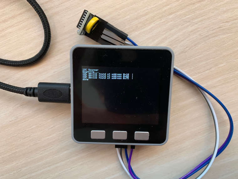
So I am assuming that the address is 0x68. When I unplug it, here is whan I scan :
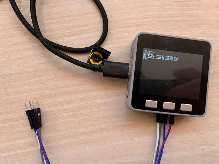
So I am assuming that I still see the 0x68 because it is the address of the MPU 6886, right ?
When I am running the I2C scan with the first DS3231 RTC, here is what I can scan :
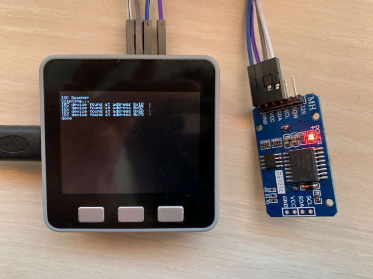
I have understood reading the datasheet of the M5 stack that :
0x10 is for BMM150 sensor
0x75 is for IP5306
0x68 is for MPU6886 (as you said)If I disconnect the RTC from my M5stack, I do not find the 0x57 anymore of the scan. How can we explain it ? (I understand that even if the RTC is 0x68 we still see it because the MPU6886 as the same adress).
By the way, being quite new to the M5Stack world and arduino world in general, I do not have a clue on the way to setup a second I2C bus using other GPIOs. Could you help me on this way please ?
Thank you very much for your help,
Morgan
-
Hello @morguane
you are welcome. As I have mentioned before your RTC module seems to contain a second IC (Memory chip: AT24C32 - storage capacity 32 KB) which uses I2C address 0x57. That is why you can see 0x57 with the module attached, but don't see 0x57 w/o the module attached.
Re second I2C bus: there are at least two I2C buses available
WireandWire1. If no arguments are given, default GPIOs are used, eg. GPIO21 and GPIO22 on the M5Stack Gray. But the GPIOs can be defined freely with arguments, e.gWire1.begin(16, 17).Here is an I2C scanner example which scans both I2C buses:
#include <M5Stack.h>

#define USE_SECOND_I2C_BUS // GPIO16 and GPIO17

int textColor = YELLOW;

void setup()
{
  M5.begin(true, false, true, true);
  M5.Power.begin();

#ifdef USE_SECOND_I2C_BUS
  Wire1.begin(16, 17);
#endif // USE_SECOND_I2C_BUS

  M5.Lcd.begin();
  M5.Lcd.fillScreen(BLACK);
  M5.Lcd.setCursor(0, 0);
  M5.Lcd.setTextColor(YELLOW);
  M5.Lcd.setTextSize(2);
  M5.Lcd.fillScreen(BLACK);
  M5.Lcd.setCursor(0, 0);
  M5.Lcd.println("M5Stack I2C Tester");
  delay(1000);
  M5.Lcd.fillScreen(BLACK);
}

void loop()
{
  int address;
  int error;

  M5.Lcd.setCursor(0, 0);
  M5.Lcd.println("0: scanning Address [HEX]");
  for(address = 1; address < 127; address++)
  {
    Wire.beginTransmission(address);
    error = Wire.endTransmission();
    if(error == 0)
    {
      M5.Lcd.print(address,HEX);
      M5.Lcd.print(" ");
    }
    else M5.Lcd.print(".");
    delay(10);
  }

#ifdef USE_SECOND_I2C_BUS
  M5.Lcd.println();
  M5.Lcd.println("1: scanning Address [HEX]");
  for(address = 1; address < 127; address++)
  {
    Wire1.beginTransmission(address);
    error = Wire1.endTransmission();
    if(error == 0)
    {
      M5.Lcd.print(address,HEX);
      M5.Lcd.print(" ");
    }
    else M5.Lcd.print(".");
    delay(10);
  }
#endif // USE_SECOND_I2C_BUS

  if(textColor == YELLOW) textColor = GREEN;
  else textColor = YELLOW;
  M5.Lcd.setTextColor(textColor, BLACK);
}
Whereever you want to use the second I2C bus (instead of the first one), replace
WirewithWire1in the appropriate locations. (This also applies to any libraries you are going to use which might haveWirehard coded - but you can modify that in your local copy of the library.)Cheers
Felix -
OMG it works.
Thank you sooo much !I put here some details if it can help someone else.
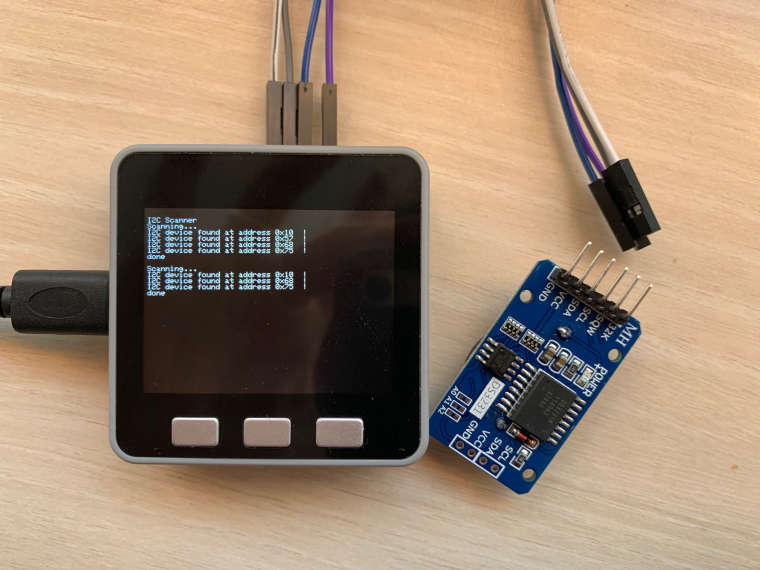
First, here is the result of your double I2C scan :
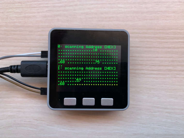
We can clearly see that the first bus we have 10, 68 and 75 (as we spoke before), and then on the second one we have 68 (the RTC) and 57 (his memory).
Then , I changed all the functions of my RTCLib library (Adafruit library for using RTC modules).
And now my previous code is working fine :#include "RTClib.h" #include <M5Stack.h> RTC_DS3231 rtc; char daysOfTheWeek[7][12] = {"Sunday", "Monday", "Tuesday", "Wednesday", "Thursday", "Friday", "Saturday"}; void setup () { Serial.begin(9600); M5.begin(true, false, true, true); M5.Power.begin(); Wire1.begin(16,17); rtc.begin(); } void loop () { M5.update(); M5.Lcd.fillScreen(BLACK); //Getting the time DateTime now = rtc.now(); M5.Lcd.setCursor(30,80); //Printing it on M5 Lcd M5.Lcd.print(now.year(), DEC); M5.Lcd.print('/'); M5.Lcd.print(now.month(), DEC); M5.Lcd.print('/'); M5.Lcd.print(now.day(), DEC); M5.Lcd.print(" ("); M5.Lcd.print(daysOfTheWeek[now.dayOfTheWeek()]); M5.Lcd.print(") "); M5.Lcd.print(now.hour(), DEC); M5.Lcd.print(':'); M5.Lcd.print(now.minute(), DEC); M5.Lcd.print(':'); M5.Lcd.print(now.second(), DEC); M5.Lcd.println(); delay(3000); }Morgan
-
-
@morguane I just saw your topic (of almost a year ago). I guess you solved your problems with the external RTC by now. But anyway liked to inform you about the repo I published on GitHub, using a D3231 RTC with a M5Stack Core1 (BASIC). DS3231 on M5Stack_DS3231_uRTC.
Regards,