TimerCam Power/Wake button docs – G38 instead of G37
-
Hello,
I recently bought a Timer Camera board and have been using it with Arduino/PlatformIO. I had some issues trying to detect presses of the Power/Wake button in my code, and found several threads in this forum from people who apparently had the same issue. The problem is that the M5Stack docs have a table like this:
BUTTON TimerCamera BUTTON G37Button presses are definitely not registered on this pin.
By trial and error I attempted to read various pins and eventually found that the button pin is number
38, and not37.I used the
gpio_*functions fromframework-arduinoespressif32to read the pin; here's some sample code that should work:#define BUTTON_PIN GPIO_NUM_38 void setup() { Serial.begin(9600); while (!Serial); gpio_reset_pin(BUTTON_PIN); gpio_set_direction(BUTTON_PIN, GPIO_MODE_INPUT); gpio_set_pull_mode(BUTTON_PIN, GPIO_PULLUP_ONLY); } void loop() { int button_state = gpio_get_level(BUTTON_PIN); if (button_state == HIGH) { Serial.println("Button pressed!"); } }I believe the Arduino pin functions would work too, e.g.
#define BUTTON_PIN GPIO_NUM_38

void setup() {
    pinMode(BUTTON_PIN, INPUT);
}

void loop() {
    int button_state = digitalRead(BUTTON_PIN); // HIGH when pressed
}
If someone from M5Stack reads this, could they please update the docs so that others can avoid spending time figuring this out? Or if someone knows how I could report this to them, I'd be happy to send them an email about it.
Here are the other threads I found about it, none with an answer unfortunately:
-
Hello @fried_chips
thank you for reporting - you made me curious so I checked the traces (with a multi-meter) on my Timer Camera board and the Power/Wake button (through a diode) is connected to GPIO37 as mentioned in the documentation and as it is on the schematic.
However you are correct in that it doesn't work. The reason is GPIO34-39 are input only GPIOs and they lack internal pull-up or pull-down capabilities. And since there is no external pull-up resistor on the board, reading the Power/Wake button doesn't work. In my case it always reports LOW.
That said, after adding an external pull-up resistor, I can now read the Power/Wake button state correctly through GPIO37. Unpressed it reports HIGH (external pull-up) and pressed (connected to GND) it reports LOW.
BTW: I did try to read GPIO38, as you suggest, and interestingly it works, however the states are the other way round. Pressed reports HIGH and unpressed reports LOW. Looking at the schematics I think it 'works' because no battery is attached to my board. And GPIO38 is used to read the battery voltage.
So my conclusion is that the documentation is correct, but unfortunately on the Timer Camera board the required external pull-up resistor has been forgotten.
Thanks
Felix -
Hi @felmue, thanks for the reply and sorry for the delay in responding in turn.
I thought at first that this might have something to do with pull-up resistors, before discovering that I could read the value from
GPIO38at which point I figured it might be a documentation issue instead. I did notice that the unpressed value wasLOWand the pressed value wasHIGH, and did find this unexpected.I think I understand what you are saying about adding an external pull-up resistor, but I can't figure out how you did this. There's very little space on the board, no exposed row of pins, and very few silkscreened markings identifying various pins or even components, so how did you do this? The way I understand your post is that you're saying you soldered (or somehow connected) a pull-up resistor between
GPIO37andVCC_3V3… is that right? Could you maybe share a bit more information about this process?Alternatively I was wondering if there was any way that you could think of to still detect button presses, and if so if you could please share a code sample for it.
Thanks again!
-
Hello @fried_chips
it's a job I've done under the microscope. I found the respective points (GPIO 37 and 3.3 V) looking at the schematic and using a muti-meter.
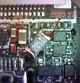
I used a 15 k pull-up resistor (marked 1502) simply because I had that in SMD format.
Note: Please be careful if you attempt to replicate this. I cannot take any responsibility if something goes wrong. You are doing this on your own risk.
Thanks
Felix -
@felmue oh wow! Thanks for sharing the photo and taking the time to annotate it. Indeed this is way outside of my capabilities, and I wouldn't expect more owners of this board to have the gear, SMD components, or SMD reworking experience to attempt this mod.
I'm definitely not going to try, and your post can probably serve as a warning to anyone tempted to do something similar themselves. I'm fine with using
GPIO38as a weird inverted button for now while I write code for this board and have it nearby plugged into USB power, and if I ever run it off of a battery it'll likely be in a setting where I communicate with it over WiFi rather than with a physical interaction.I hope that M5Stack can address this issue with a built-in pull-up resistor some time in the future, as it stands this button is only partially usable and there's evidence on this forum that other users have encountered this issue in the past.
-
@fried_chips I finally got to this thread. Thank you, I've been looking for the solution of this problem. and I'm glad to have found it.
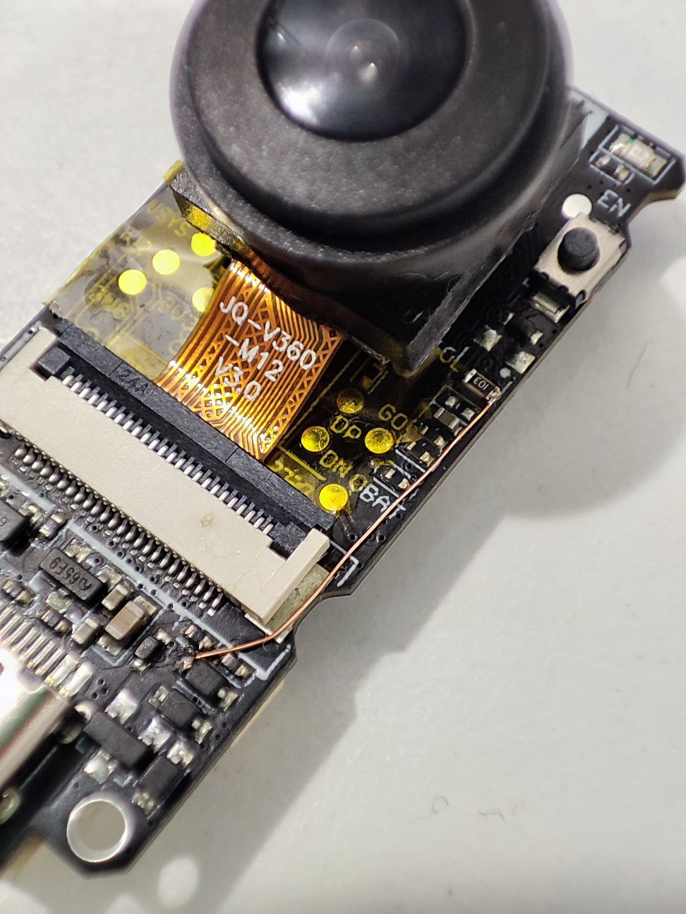
I installed a pull-up resistor this route.
Hello! It looks like you're interested in this conversation, but you don't have an account yet.
Getting fed up of having to scroll through the same posts each visit? When you register for an account, you'll always come back to exactly where you were before, and choose to be notified of new replies (either via email, or push notification). You'll also be able to save bookmarks and upvote posts to show your appreciation to other community members.
With your input, this post could be even better 💗
Register Login