Facial Recognition and Tracking Project with mechArm M5stack
-
Long time no see, I'm back.
I'll give a report on the recent progress of the facial recognition and tracking project. For those who are new, let me briefly introduce what I am working on. I am using a desktop six-axis robotic arm with a camera mounted on the end for facial recognition and tracking. The project consists of two modules: one for facial recognition, and the other for controlling the movement of the robotic arm. I've previously discussed how the basic movement of the robotic arm is controlled and how facial recognition is implemented, so I won't go into those details again. This report will focus on how the movement control module was completed."
Equipment
mechArm 270M5Stack, camera
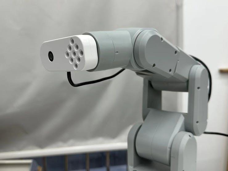
Details of the equipment can be found in the previous article.
Motion control module
Next, I'll introduce the movement control module.
In the control module, the common input for movement control is the absolute position in Cartesian space. To obtain the absolute position, a camera and arm calibration algorithm, involving several unknown parameters, is needed. However, we skipped this step and chose to use relative displacement for movement control. This required designing a sampling movement mechanism to ensure that the face's offset is completely obtained in one control cycle and the tracking is implemented.
Therefore, to quickly present the entire function, I did not choose to use the hand-eye calibration algorithm to handle the relationship between the camera and arm. Because the workload of hand-eye calibration is quite large.
The code below shows how to obtain parameters from the information obtained by the facial recognition algorithm.
Code:
_, img = cap.read()
# Converted to grey scale
gray = cv2.cvtColor(img, cv2.COLOR_BGR2GRAY)
# Detecting faces
faces = face_cascade.detectMultiScale(gray, 1.1, 4)
# Drawing the outline
for (x, y, w, h) in faces:
if w > 200 or w < 80:
#Limit the recognition width to between 80 and 200 pixels
continue
cv2.rectangle(img, (x, y), (x+w, y+h), (255, 0, 0), 3)
center_x = (x+w-x)//2+x
center_y = (y+h-y)//2+y
size_face = w
The obtained variables, center_x, center_y, and size_face, are used to calculate the position. Below is the code for the algorithm that processes the data to control the movement.
run_num = 20
#Control cycle of 20 frames
if save_state == False:
# Save a start point (save_x, save_y)
save_x = center_x
save_y = center_y
save_z = size_face
origin_angles = mc.get_angles()
print("origin point = ", save_x, save_y, origin_angles)
time.sleep(2);
current_coords = mc.get_coords()
save_state = TRUE
else:
if run_count > run_num: # Limit the control period to 20 frames
run_count = 0
# Recording relative offsets
error_x = center_x - save_x
error_y = center_y - save_y
error_z = size_face - save_z
# Pixel differences are converted into actual offsets, which can be scaled and oriented
trace_1 = -error_x * 0.15
trace_z = -error_y * 0.5
trace_x = -error_z * 2.0
# x/z axis offset, note that this is open loop control
current_coords[2] += trace_z
current_coords[0] += trace_x
#Restricting the Cartesian space x\z range
if current_coords[0] < 70:
current_coords[0] = 70
if current_coords[0] > 150:
current_coords[0] = 150
if current_coords[2] < 220:
current_coords[2] = 220
if current_coords[2] > 280:
current_coords[2] = 280
# Inverse kinematic solutions
x = current_coords[0]
z = current_coords[2]
# print(x, z)
L1 = 100;
L3 = 96.5194;
x = x - 56.5;
z = z - 114;
cos_af = (L1*L1 + L3*L3 - (x*x + z*z))/(2*L1*L3);
cos_beta = (L1*L1 - L3*L3 + (x*x + z*z))/(2*L1*math.sqrt((x*x + z*z)));
reset = False
# The solution is only applicable to some poses, so there may be no solution
if abs(cos_af) > 1:
reset = True
if reset == True:
current_coords[2] -= trace_z
current_coords[0] -= trace_x
print("err = ",cos_af)
continue
af = math.acos(cos_af);
beta = math.acos(cos_beta);
theta2 = -(beta + math.atan(z/x) - math.pi/2);
theta3 = math.pi/2 - (af - math.atan(10/96));
theta5 = -theta3 - theta2;
cof = 57.295 #Curvature to angle
move_juge = False
# Limits the distance travelled, where trace_1 joint is in ° and trace_x/z is in mm
if abs(trace_1) > 1 and abs(trace_1) < 15:
move_juge = True
if abs(trace_z) > 10 and abs(trace_z) < 50:
move_juge = True
if abs(trace_x) > 25 and abs(trace_x) < 80:
move_juge = True
if (move_juge == True):
print("trace = ", trace_1, trace_z, trace_x)
origin_angles[0] += trace_1
origin_angles[1] = theta2*cof
origin_angles[2] = theta3*cof
origin_angles[4] = theta5*cof
mc.send_angles(origin_angles, 70)
else:
#Due to the open-loop control, if no displacement occurs the current coordinate value needs to be restored
current_coords[2] -= trace_z
current_coords[0] -= trace_x
else:
# 10 frames set aside for updating the camera coordinates at the end of the motion
if run_count < 10:
save_x = center_x
save_y = center_y
save_z = size_face
run_count += 1
In the algorithm module, after obtaining the relative displacement, how to move the arm? To ensure the movement effect, we did not directly use the coordinate movement interface provided by Mecharm, but instead added the inverse kinematics part in python. For the specific posture, we calculated the inverse solution of the robotic arm and transformed the coordinate movement into angle movement to avoid singular points and other factors that affect the Cartesian space movement. Combining the code of the facial recognition part, the entire project is completed.
Let's look at the results together.
https://youtu.be/dNdqrkggr9cNormally, facial recognition has high computational requirements. Its algorithm mechanism repeatedly calculates adjacent pixels to increase recognition accuracy. We use MechArm 270-Pi, which uses a Raspberry Pi 4B as the processor for facial recognition. The computing power of the Raspberry Pi is 400MHZ. Due to the insufficient computing power of the Raspberry Pi, we simplified the process and changed the recognition mechanism to only a few times of fuzzy recognition. In our application, the background needs to be simpler."
Summary
The facial recognition and robotic arm tracking project is completed.Key information about the project:
● In the case of low computing power, set a simple usage scenario to achieve smooth results
● Replace complex hand-eye calibration algorithms with relative position movement and use a sampling movement mechanism to ensure that the face's offset is completely obtained in one control cycle and the tracking is implemented.
● In python, added the inverse kinematics part, calculated the inverse solution of the robotic arm for specific postures, and converted the coordinate movement into angle movement to avoid singular points and other factors that affect the Cartesian space movement.
Some shortcomings of the project:
● There are certain requirements for the usage scenario, and a clean background is needed to run successfully (by fixing the scene, many parameters were simplified)
● As mentioned earlier, the computing power of the Raspberry Pi is insufficient, using other control boards, such as Jetson Nano (600MHZ) or high-performance image processing computers, would run smoother.
● Also, in the movement control module, because we did not do hand-eye calibration, only relative displacement can be used. The control is divided into "sampling stage" and "movement stage". Currently, it is preferable to require the lens to be stationary during sampling, but it is difficult to ensure that the lens is stationary, resulting in deviation in the coordinates when the lens is also moving during sampling.
Finally, I would like to specially thank Elephant Robotics for their help during the development of the project, which made it possible to complete it. The MechArm used in this project is a centrally symmetrical structured robotic arm with limitations in its joint movement. If the program is applied to a more flexible myCobot, the situation may be different.
If you have any questions about the project, please leave me a message below.
-
This item is reproduced from a user project
-
This looks great, I have a myCobot would I be able to implement it with this code?
-
Nice, the more projects you share, the more I want one to play with.
UIFlow, so easy an adult can learn it!
If I don't know it, be patient!
I've ether not learned it or am too drunk to remember it!
Author of the WIP UIFlow Handbook!
M5Black, Go, Stick, Core2, and so much more it cant be fit in here! -
@pengyuyan Of course! You need to do some modified to the code!
-
@ajb2k3 Thanks for your support, we will share more interesting projects in the future.If you want a mechArm, please contact us!
-
Hi
Can you explain how to convert pixel differences into actual offsets? How calculate the numbers you multiply by error_x,y,z?
Hello! It looks like you're interested in this conversation, but you don't have an account yet.
Getting fed up of having to scroll through the same posts each visit? When you register for an account, you'll always come back to exactly where you were before, and choose to be notified of new replies (either via email, or push notification). You'll also be able to save bookmarks and upvote posts to show your appreciation to other community members.
With your input, this post could be even better 💗
Register Login