Using seeed studio onewire thermocouple amp with m5 stack
-
Hi
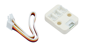
I managed to pickup a couple of thermocouple amps that are made by seed studios. These use a grove connector but not i2c rather one wire bus.
I'm trying to hook this up to my m5stack basic via the grove port and program using arduino ide however it's not working like it should.
Seed studios has an Arduino library for the thermocouple amp that I have imported in fine. This includes the OneWire bus library.
To initialize OneWire I need to provide a pin. I'm assuming that pin26 is the correct pin if using the grove connector on the m5 stack? Am i right. The yellow wire on grove cable maps to pin26 doesnt it?
I've tried this and can't get any devices found when I do the scan using the library.
Do I have to do anything special in code to get this going apart from the normal m5.begin
Wondering whether others may have used thermocouples not thermistors before to.
Rob
-
Ok, so I can get this to work if I run the PWR, GRND and DINOUT (Yellow) from the thermocouple amp and into pins 5V/3.3V, G and G5 using jumper wires instead of physical GROVE port on m5stack.
I then changed my code so the OneWire bus was using pin GPIO pin 5. Everything worked as expected. All good.
However, I am looking for something a bit more robust for prototyping then jumper wires i.e physical GROVE connectors with a hub for multiple. I noticed on the product site that alot of the units have a GROVE connector however they are NOT i2C i.e potentiometer unit so I figured I could do the same with this type of connection which is not I2C but one wire. I guess my assumption was wrong. I do see in the doco refrences to GROVE A and GROVE B? What is the difference from a connection point of view and from a programming point of view?
However now that I have got it working I can only assume the physical GROVE port on the M5stack is just for I2C devices. Am I correct? Is I2C enabled by default or should I be turning it off for non I2C stuff?
I also have a GROVE I2C mosfet that I need to incorporate into my build which I'm pretty sure will work with the GROVE port. But I really wanted to be able to have a hub where I just added the various sensors etc without jumper wires
Thanks
Rob
-
So sorry for my late reply. We are too busy. If you are anxious about the hub problem, you can send the email to me. tech@m5stack.com
You means a couple of thermocouple amps works well with M5Stack. So which port do you use? Port A or B? I think onewire function can works well whether the OneWire pin belongs to Port A or B.
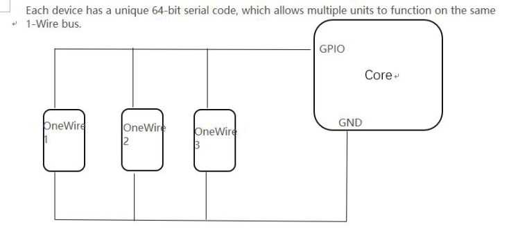
I have draw a picture for OneWire device cascade just now.
I think the HUB unit will help you. It's just my guess. I dare not be 100% sure
-
@rob-biernat which M5Stack or Stick are you using?
The M5Stacks and Sticks have an I2C grove port (port A) but this is also a digital I/O port in that it can read or write 0 or 1 values (on or off) I am currently triggering a relay unit from the port.
The M5Go base has has 2 additional port which are multi I/O (port b) and UART (port C) Unlike Arduinos, the esp32 which powers the M5Stack has no set pin functions and all pins can be used for a range of functions.
When using Port A Yellow is SCL (pin 22) and white is SDA (pin 21) and need to be defined.
I have started to document the different functions of the grove connector and you can find them on pg 19 and 20 of my WIP book here https://github.com/Ajb2k3/UIFlowHandbook/blob/master/UIHB1404192.pdf