@jwd3ca NO!
Unfortunately I didn't find a solution.
As written above, I just left the PSRAM disabled, as i don't need it in my application.
Posts made by grelm
-
RE: Problems with using library M5.stack.h and functions like M5.Lcd.print()posted in Arduino
-
RE: Problem when connecting more than 3 DS18B20 temperature sensors! - solved!posted in PROJECTS
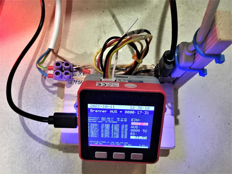
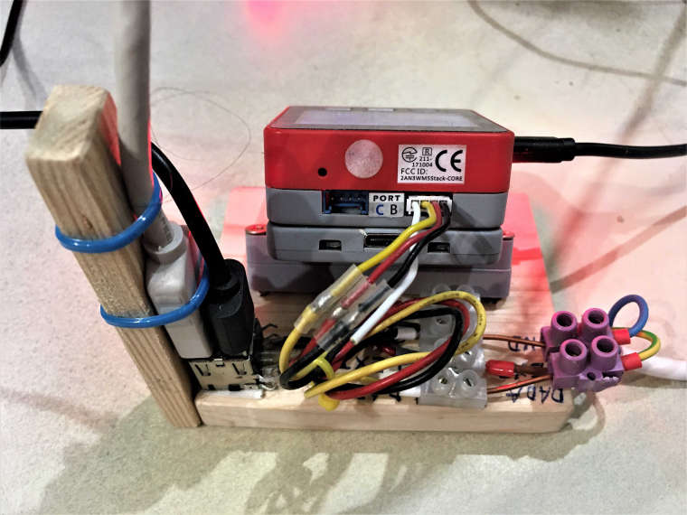
@saiaman01 What exactly do you want to know or see?
May be the two pictures are of help to you.
Or do you need a schematic or any explanation?Picture 1
Picture 2
-
RE: Connect DS18B20 to Grove Port A?posted in PROJECTS
I am happy to read that the post was helpful.
Which changes did you apply to make it work? -
RE: Recording mowing path of lawn robotposted in PROJECTS
@devilstower Thanks again to Devilstower!
Sounds very promising and worth continuing with my project.
I'll keep you informed (will take some time). -
RE: Recording mowing path of lawn robotposted in PROJECTS
Many thanks to Devilstower!
I am aware of these accuracy-issues of GPS readings (analog measurements in general).
My plan is to read in the GPS-Readings as fast as possible and store time and value on a SD-card.
Evaluation und graphical display of the stored values will be done offline on a PC.
This will allow to do any kind of averaging like "moving average".
I am hoping of getting an accuracy of < 0,5 meter (3 sigma) at a given static position.
So far I have no idea on how many measurements need to be done and averaged to get this accuracy.
I also do not know, how fast GPS-measurements can be done and if there is a trade off between measurement rate and accuracy.Do you have any further informations and/or recommendations on "accurate" GPS-measurement-hardware which is compatible to the M5Stack-Fire?
-
RE: Recording mowing path of lawn robotposted in PROJECTS
Additional question: Does anyone know a way to read the GPS position from an iPhone with a M5Stack Fire (e.g. in 1-second intervals)?
-
Recording mowing path of lawn robotposted in PROJECTS
With a M5Stack Fire plus a GPS module, I want to record the mowing path or the position of a lawn robot, record it and display it offline (possibly live) on a tablet or a PC.
Programming would be preferred with Arduino.
Has anyone tried this or seen such or similar applications (such as recording the jogging path or a motorcycle tour)?
I would be pleased with any feedback. Thank you very much.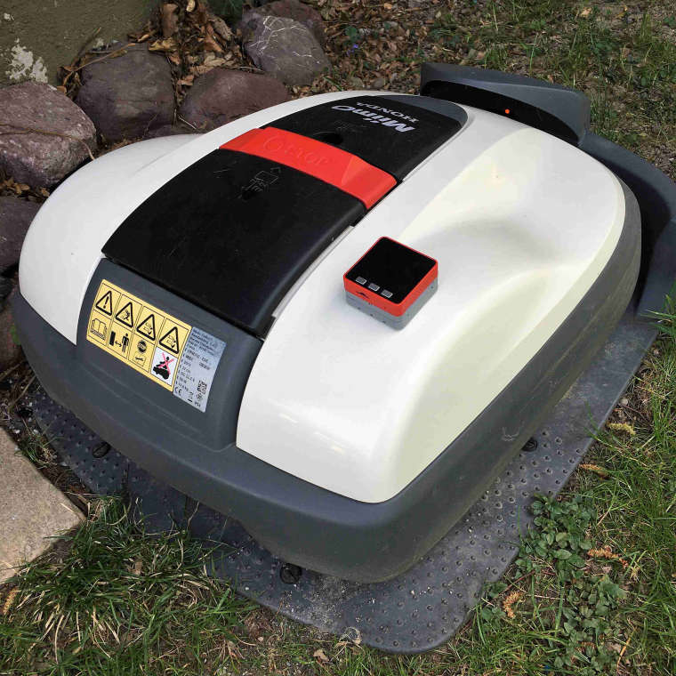
-
RE: M5StickC Nixie tube Clockposted in PROJECTS
If @ajb2k3's suggestion didn't help, you could look into this:
I am not sure, but did you this: (from: https://github.com/McOrts/M5StickC_Nixie_tube_Clock)
Update Nixie Tube images
Execute the lcd-image-converter.exe include in this repository.
" Png or Jpg is read from File->Open Menu. The image will be displayed when loaded.
Select: Option->Conversions Menu. The top Preset: selects "Color R5G6B5".
Select: Image tap and select “8 bit” for Block size :. Press "OK".
The example "vfd_35x67_8.c" is output by "Convert ..." in File-Convert Menu. Know in advance the destination path. Tick: Import All Images You can also output all the images with “Convert ... all”.
Edit .c converted file. You will get an error as it is, so fix it with your editor." Change: "Static const uint8_t image_data_vfd_35x67 [4690] = {" at the top of the file deleting "image_data_" as result of "static const uint8_t vfd_35x67_8 [4690] = {".
At the bottom of delete de entire line: "const tImage vfd_35x67 = {image_data_vfd_35x67, 35, 67, 8};
Save the example "vfd_35x67_8".c***May be you could send us the complete compiler-error-listing again, as the board-selection is correct now.
(Btw: as I don't have a M5Stick-C, i can not check even my own suggestions!)
-
RE: M5StickC Nixie tube Clockposted in PROJECTS
Without wanting to anticipate @ajb2k3 :
Your first screenshot says "Fehler beim Kompilieren für das Board ESP32 Pico Kit" and this board is also listed in the lower right corner of the screenshot.
I think, that you should first change the board-Type in the Arduino IDE under 'Tools/Werkzeuge' - 'Board/???' - .... to: 'M5Stick-C' and than try to compile again.
May be (and I hope) it helps ... -
RE: M5Stack Capacitive TouchScreenposted in SOFTWARE
@ajb2k3 said in M5Stack Capacitive TouchScreen:
shock you don't know our Jimmy?shock
I'm sorry I didn't know Jimmy Lai before! 😢
However, now, after watching https://www.youtube.com/watch?v=FLcXPGfMqbM I do! 👍
It is never to late to learn! 😉 -
RE: M5Stack Capacitive TouchScreenposted in SOFTWARE
@ajb2k3 said in M5Stack Capacitive TouchScreen:
Jimmie has not been very forthcomming with the specs ...
@ajb2k3: Just out of interest: who is Jimmie?
-
RE: M5Stack Capacitive TouchScreenposted in SOFTWARE
Water resistant version with touchscreen ?!?! 👍
When and where will it be available?
Technical data already available?
I definitely want it! -
RE: M5Stack Capacitive TouchScreenposted in SOFTWARE
May be a misunderstanding!?
In the description under "ESP32 Features" it is listed: "10x capactive touch interface".
Meaning: some ESP32 inputs can be used as 'Touch Inputs' -
RE: Looking for unit to read the status of several relay-contacts via OneWire-busposted in Units
Hi!
Are there really no answers to my questions?
Thanks - grelm -
RE: Looking for unit to read the status of several relay-contacts via OneWire-busposted in Units
My project reads 10 temperature sensors DS18B20 via a OneWire.bus (or 1-wire-bus) which is connected to the Grove B port of the M5Stack Fire.
In addition to those 10 temperaturesensors I would like to capture the status of relay contacts (on or off). For that I would need some kind of input device which I can connect to the existing OneWire-bus.In the meantime I found 2 devices which would possibly do the desired job:
-
DS2413 1-Wire Two GPIO Controller Breakout; PRODUCT ID: 1551 - https://www.adafruit.com/product/1551
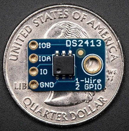
-
ClosedCube Duo DS2413 - https://www.amazon.de/closedcube-DS2413-1-Wire-ansteuerbaren-Schalter-Breakout/dp/B01GBTMX3A/ref=sr_1_1?__mk_de_DE=ÅMÅŽÕÑ&keywords=ds2413&qid=1561665695&s=gateway&sr=8-1
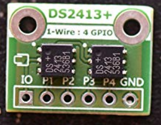
New questions:
- Has anyone already worked with these modules?
- What are your experiences with these modules?
- Are there usable Arduino librararies for these modules?
Thanks - grelm
-
-
RE: Looking for unit to read the status of several relay-contacts via OneWire-busposted in Units
Hi again!
Is really nobody reading relay-contacts via the OneWire-bus?
Or is there a better alternative solution for such an application? How?
Thanks - grelm -
RE: Problems with using library M5.stack.h and functions like M5.Lcd.print()posted in Arduino
Hi - it's me again!
After playing around with almost "everything", I found out:
Everything is working fine, after DISABLING the PSRAM in ARDUINO/TOOLS.Does that mean, that PSRAM can not be used at all?
Is there any explanation for this behaviour?Thanks - grelm
-
Problems with using library M5.stack.h and functions like M5.Lcd.print()posted in Arduino
Hi!
I am having problems by using the M5.Stack.h library. I am kind of stuck with it and would like to ask for some help on it.
For software developement and testing I am using the Arduino IDE 1.8.9 with the M5.stack.h library 0.2.7.
After uploading various program examples which are printing to the Lcd-screen of the M5Stack-Fire, everything works as expected.Problem-description:
As soon as I add even a single additional code lines like „M5.Lcd.println(„test“);“ or „M5.Lcd.setCursor(0,0);“ further down in the program and upload it to the M5Stack-Fire, the programm does not work at all anymore. Not even the printing at the very beginning oft the programm appears on the LCD.
No error message is displayed in the Arduino IDE during compiling and uploading of the program.Questions:
Is there any known issue, about this behaviour?
Are there any recommendations on how to attack and solve this problem?Thanks for any feedback - grelm
-
Looking for unit to read the status of several relay-contacts via OneWire-busposted in Units
Hi!
For one of my projects I would like to read the status of several relay contacts with a OneWire-Device connected to Grove port B.
I know, there is the DS2408 IC, but I am looking for a "more complete" unit, ready to connect the relay contacts and with a grove connector.
I would like to ask the community, if anybody is aware of such a unit and where I could buy it.
Thanks - grelm -
RE: Problem when connecting more than 3 DS18B20 temperature sensors! - solved!posted in PROJECTS
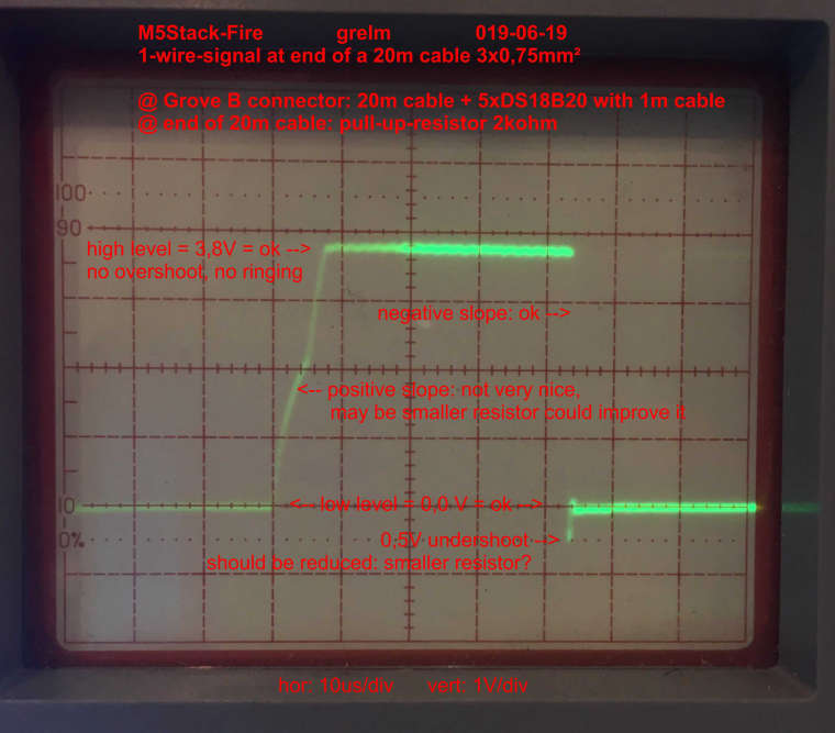
Measuremnts of supply-voltage and signal-shape:
- Voltage of +5V-line: +5,07 V at Grove-connector and at end of 20m-cable = ok = no voltage drop (measured with DMM)
- Signal-shape of 1-wire-signal-line: see attached photo below = ok, but seee comments in photo (measured with oscilloscope Sony/Tektronix 335)
