I found my answer. Looks like I can use either pins 35 or 36. Considering that I have comms on those two pins, 36 is the RX pin, so I can just toggle the RX input to wake the Core2 from Deep Sleep.
Sir Michael
I found my answer. Looks like I can use either pins 35 or 36. Considering that I have comms on those two pins, 36 is the RX pin, so I can just toggle the RX input to wake the Core2 from Deep Sleep.
Sir Michael
Are any of the ESP32 RTC Pins exposed that I can use to wake the Core2 AWS?
I can't figure out which pins could be used to wake from a Deep Sleep.
Sir Michael
yuyun2000,
I wasn't able to get my structure to pass correctly. I ended up not only changing the double to a float, but I also changed it to another uint16_t. There was still a 1 byte difference in the sizes of the structure (Nano was 13, M5Stack was 14). I added the "uint8_t pad1" to the Nano so it was then 14 also. The comms routines that I have now shows that they both return a 0 (successful) but the data doesn't come across like it does with the Nano to Nano testing.
I've decided to give up on sending the Structure and just assemble the data into a String Array and send that. I have it working as a String, but I'm changing it over to use a null terminated Character Array.
Thanks Anyway, it was fun trying!
Sir Michael
I'm not an expert at this, but perhaps I can help some...
I think you are using an ESP32 for a board.
First of all, did you install the M5Stack boards on your Arduino IDE? Reference this link:
https://docs.m5stack.com/en/arduino/arduino_board
Make sure that you select the board correctly in the IDE:
Tools/Board/M5Stack/M5Core2
Make sure that you have the correct Comm Port. Open your Device Manager, unplug the USB cable from the M5Stack and see which Comm Port goes away. Plug it back in and use that Comm Port Number for the M5Core2.
I'd suggest starting with one of the Examples from the IDE:
File/Examples/M5Core2 (you may have to scroll al LONG way down). Make sure you can load one of the example files to get started. I'd suggest you look under "M5Unified".
Try to do all of your development using
#include <M5Unified.h>
There may be some examples that have
#include <M5Core2.h>
but these are no longer supported. All of the support is going in the the M5Unified branch so they don't have to support so many other products.
I hope this helps.
Sir Michael
yuyun2000,
Thank you for the reply. This finally explains why I've been having so much trouble.
I don't need the precision of the double, so it's not a problem to change to a float. I have tried removing the double and inserted another uint16_t, but then I had a 1 byte difference. That was a close as I had gotten so far.
I'll have to study your response more and try to understand it to get it to work, hopefully today.
Again, my sincere thanks...
Sir Michael
I've been struggling with trying to pass a structure between an Arduino NANO and an M5Stack Core2 through Serial Comms.
I can get the structure to pass correctly between two Arduino UNOs or NANOs, but when I try to get it to use on my project between a NANO and the M5Stack Core2, it fails. (Serial comms passes strings just fine!)
I finally figured out that the sizeof the Structure is reported as 15 bytes on the NANO and 24 bytes on the M5Stack Core2.
I changed my declarations from:
byte to uint8_t
int to uint32_t
on the NANO and M5.
I do also have a double in the structure:
//Use the same struct for comms both ways!
struct AmpStruct {
uint8_t bMode;
uint16_t iBand;
double dVolts;
uint16_t iAmpTemp;
uint16_t iFanOutput;
uint16_t iFwdPower;
uint16_t iRefPower;
};
//Initialize the values to create the usable structure
AmpStruct AmpData = {0, 0, 0, 0, 0, 0, 0};
Can anyone tell me what the difference is? Is there a way to make the structure the same between the two? There has to be way to declare the variables so they take up the same number of bytes on the two platorms.
I do have the comms working by passing strings, but I'd like to use the Structure within the communications.
Sir Michael
I tried to draw a graph using the M5.Lcd.fillRect() but I can't seem to be able to load the colors into a Variable:
#include <M5Unified.h>
void setup() {
Serial.begin(115200);
auto cfg = M5.config();
cfg.led_brightness = 255;
M5.begin(cfg);
}
void loop() {
//White
M5.Lcd.fillRect(10, 20, 50, 10, WHITE);
uint32_t Color = WHITE;
Serial.print("Color WHITE = ");
Serial.println(Color);
M5.Lcd.fillRect(10, 40, 50, 10, Color);
Color = TFT_WHITE;
Serial.print("Color TFT_WHITE = ");
Serial.println(Color);
M5.Lcd.fillRect(10, 60, 50, 10, Color);
//Green:
M5.Lcd.fillRect(80, 20, 50, 10, GREEN);
Color = GREEN;
Serial.print("Color GREEN = ");
Serial.println(Color);
M5.Lcd.fillRect(80, 40, 50, 10, Color);
Color = TFT_GREEN;
Serial.print("Color TFT_GREEN = ");
Serial.println(Color);
M5.Lcd.fillRect(80, 60, 50, 10, Color);
while (1) ;
}
https://drive.google.com/file/d/1bo_OfbBQ5SA3hC-_SwRJyUKUOu8QNMk_/view?usp=sharing
I'm sure this is an issue with all the other graphical calls, not just the fillRect().
How do I find out what the Color variable is in the fillRect(x,y,z,d,**COLOR**) variable is?
Is this a bug?
I'm using an M5 Core2 AWS.
Sir Michael
I finally figured it out, even after trying all of the examples in the SerialBluetooth.h example directory on the M5Stack Core2.
I finally found that I had to Initialize the Bluetooth settings on my device, after that, the connections worked find.
Sir Michael
Felix,
I had tried your suggestion, but the covered buttons would still re-act. With some more playing, I think that I could have gotten it to work, but I had re-designed the interface to use the
M5.BtnA.wasReleasedAfterHold());
to substitute for the on-screen buttons.
I do sincerely appreciate your help!
Sir Michael
I'm trying to get Bluetooth to work with an M5Stack, Core2 AWS to pass Serial Data.
There is an M5Unified.h example for Bluetooth:
M5Unified.h Bluetooth Example
but it's so obfuscated, I can't make heads or tails of how to extract some simple Bluetooth commands out of it. PLUS, I can't get it to compile...
I've had Bluetooth running on an ESP32 WROOM using BluetoothSerial.h (previous project), it connects and passes data. If I use the same Library on the M5Core2 (with the M5Unified.h, latest version) I can see the M5Stack Bluetooth on my Bluetooth device where I get the data (ICOM IC-705), it's discovered when I search, but it won't connect.
Using this simple code:
//ESP32 Specific:
#include "BluetoothSerial.h"
#if !defined(CONFIG_BT_ENABLED) || !defined(CONFIG_BLUEDROID_ENABLED)
#error Bluetooth is not enabled! Please run `make menuconfig` to and enable it
#endif
BluetoothSerial SerialBT;
void setup()
{
Serial.begin(115200);
SerialBT.begin("IC-705-ESP"); //Bluetooth device name
Serial.println("The device started, now you can pair it with bluetooth!");
}
void loop() {
while(1);
}
I can connect with the ESP32 WROOM (using ESP32 Dev Module) but it won't work with the M5Stack, Core2.
Is there something I'm missing, or can someone point me in the direction of some more simplified Bluetooth code for the M5Core2?
I tried others like one that was:
#include <M5Stack.h>
#include <BLEDevice.h>
#include <BLEUtils.h>
#include <BLEServer.h>
#include <BLE2902.h>
but again, that didn't work...
Sir Michael
Felix,
The only thing that I'm missing with it is the commands to be able to ".erase" and show again. I tried to check the options (adding the "." and checking what options are available, but I didn't find anything that seemed like it would work.. I'm not sure how to erase, or would I just do a clear screen and recreate it?
Sir Michael
Felix,
Thanks for the example. That helps.
The only thing that I'm missing with it is the commands to be able to ".erase" and show again. I tried to check the options (adding the "." and checking what options are available, but I didn't find anything that seemed like it would work.. I'm not sure how to erase, or would I just do a clear screen and recreate it?
I did play with it and added some line text, and it doesn't exhibit the same bug that the M5Core2 button graphics does when I wrote line and used the:
btn2.setLabelText("BUTTON");
It doesn't mess up the screen text by making the existing text LARGER.
Thanks,
Sir Michael
I gave up trying to create on-screen buttons and figured out a way to use the A/B/C buttons using either
M5.BtnB.wasreleased()
//or
M5.BtnB.wasReleasedAfterHold()
I was also able to get it to compile under M5Unified.h. I'll try to proceed with that.
I still need to get the Deep Sleep to work under the M5Unified.h, but I'm getting there....
Sir Michael
I had tried that. I had the exact same sequence but nothing that I would do would correct the corrupted screen. The only way was to reboot!
I would move over to the M5Unified.h, but I can't figure out how to create the same buttons:
Button BtnL(10, 190, 60, 40, false, "Dec", off_clrs, on_clrs, TL_DATUM);
//and:
BtnL.setLabel("Dec");
using the M5Unified.h library. The Touch examples are so obfuscated, I can't figure out how to get a simple button to work. I actually wrote up a bug report about this:
https://github.com/m5stack/M5Unified/issues/147
By any chance, can you point me at an example that demonstrates the on screen button [wasreleased()] operation?
Sir Michael
I'm using an M5Stack Core2 AWS on a project where I need to use on-screen buttons:
Button BtnL(10, 190, 60, 40, false, "Dec", off_clrs, on_clrs, TL_DATUM);
//and:
BtnL.setLabel("Dec");
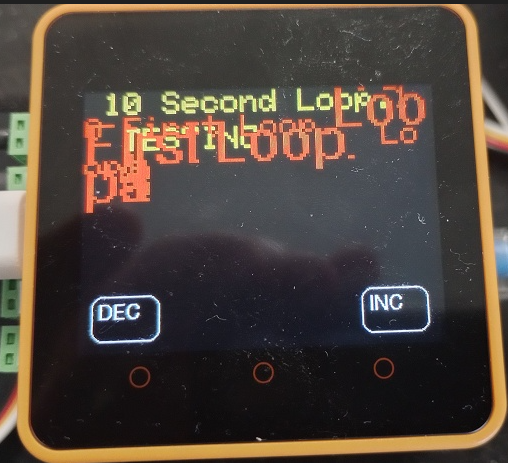
I have found that anytime I put any text into the button, the screen after the button is displayed (such as):
M5.Lcd.print(Line2.c_str());
// or
M5.Lcd.print(Line2);
the screen is corrupted and the only way that I have found to correct the problem is to reboot the Core2 device.
The corrupted screen looks like:
The only way I've found to use the on-screen buttons is to leave the button text blank and write the text above the screen button.
This very much appears to be a bug in the code.
Should I write this up as a bug on https://github.com/m5stack/M5Core2/issues/ ?
Sir Michael
I have found and tried about 8 different Arduino code examples to get sound (tone) out of the M5Core2 speaker but nothing works and I'm wondering if someone can help me.
I found an example that uses M5Unified.h that works (speaker tone output), but the M5Core2.h is NOT compatible with the M5Unified.h.
I found another "Core2_Sounds.h" that shows promise in that it compiles and downloads, but I get a continuous crash dump to the Serial Monitor.
https://github.com/Hagtronics/M5Stack-Core2/tree/main/Sound/Lib/Core2_Sounds
There is the "Example":
https://github.com/m5stack/M5-ProductExampleCodes/blob/master/Core/M5Core2/Arduino/speak/speak.ino
but I keep getting an error saying that the "driver/i2s.h" is deprecated and won't compile, even with the replacements that are suggested.
I'm at my wits end...
Does anyone have an example that works with the M5Core2.h and perhaps another library?
Sir Michael
I found what I was looking for, a simple sketch to create a button. I did some minor massages, taking from the events_buttons_gestures_rotation.ino and figured it out.
#include <M5Core2.h>
ButtonColors on_clrs = { RED, WHITE, WHITE };
ButtonColors off_clrs = { BLACK, WHITE, WHITE };
Button myButton(10, 10, 80, 60, false, "Button", off_clrs, on_clrs, TL_DATUM );
void setup() {
M5.begin();
M5.Buttons.draw();
}
void loop() {
M5.update();
if (myButton.wasReleased()) Serial.print("* ");
}
Sir Michael
I'm having trouble understanding how to use the M5Stack Core2, creating new buttons for my project.
I can use the 3 buttons (A, B & C) and for some screens, I need two more buttons, with similar properties.
I've been studying the Example: events_buttons_gestures_rotation.ino but I can't make heads or tails of it. I've added print statements to see which subroutines are executed and I don't understand what the "doRotation()" or what the swipe gestures do.
The only thing that I've discovered in playing with it is that if I press one of the buttons twice quickly that the "toggleColor" is executed.
The few comments are useless to me.
Is there a simpler example somewhere that I can use to create a few buttons when I need them for the "wasReleased()" and "wasPressedFor()" functions?
Sir Michael
I did some more studying, and came up with the following table:
I hope this is right!
Now, I'm not using the M5Stack bottom board which has the PortB and PortC, so I figure that I can use the RXD2/TXD2 pins as well as the G36 and G26 pins. I'll use those for the other 2 SoftwareSerial ports, and G27 and G19 for the other pins.
The thing that I found confusing was that they do list the pins in the M5Stack documents, but they don't really explain what is available to the user. This took a lot more work than it should have!
Sir Michael