M5StickC: turn off screen completely
-
Well that's weird because with ScreenBreath(7) the screen is still displaying something but with ScreenBreath(0) it is completely dark...
-
@florian5442 You're right but I guess the difference is too small to measure.
The official docs say that the lowest setting is 7 but clearly that is not 100% correct:brightness TFT backlight brightness (range: 7~15) -
No matter what value i use for ScreenBreath, the backlight remins on and flattens the M5StickC battery within ~5 hours. I wish to use my M5StickC as a watch and I need a much longer battery life. Can someone help me understand how to turn the display completely off?
-
@multihelix It's not going to happen. There is no way to turn the backlight or the rest of this device completely off. I think of the on board battery more like a super capacitor, it gives you enough power for a few minutes of testing but for anything else you need an external power supply with a real on/off switch.
-
I am pretty sure the screen can be completely turned off. I run the default application for awhile until it says "low battery", then I wait for awhile the screen will be completely dark (no back-lit). However, I can press the side button and toggle the LED on and off. This shows that the unit is still running. My guess is you have to talk to the OLED module via I2C and disconnect it. This qualifies as "turn off screen completely"
-
I poked around the APX192 code, and around a datasheet found here. First, there's this code:
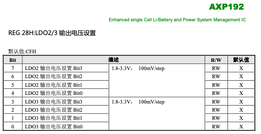
void AXP192::begin(void) {
  Wire1.begin(21, 22);
  Wire1.beginTransmission(0x34);
  Wire1.write(0x10);
  Wire1.write(0xff);  //OLED_VPP Enable
  Wire1.endTransmission();
  Wire1.beginTransmission(0x34);
  Wire1.write(0x28);
  Wire1.write(0xff); //Enable LDO2&LDO3, LED&TFT 3.3V
  Wire1.endTransmission();
A peek at the datasheet says that REG 28H is power management for LD02 and LD03. Sure thing. That's what the comment in the code above says – along with a hint that LD03 is for the TFT.
Meanwhile, REG 10H is two ON/OFF switches, for EXTEN and DC-DC2 – commented in the code as VPP_Enable. Bueno.
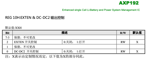
I am not sure which of EXTEN or DC-DC2 is connected to the OLED (both?), but turning either or both off will cut off the current to the OLED.
Moreover there's this code later:
  Wire1.beginTransmission(0x34);
  Wire1.write(0x12);
  Wire1.write(0x4d); //Enable DC-DC1, OLED_VDD, 5B V_EXT
  Wire1.endTransmission();
And REG 12H seems to do more of the same as 10H:
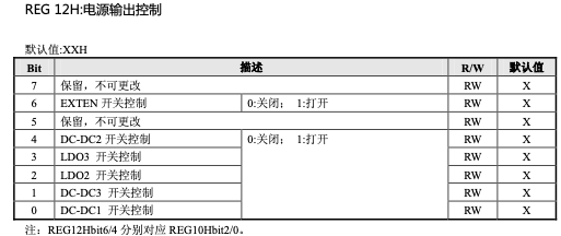
Bit 3 turns ON/OFF LD03, which, as we saw above, is supposed to be the OLED. Good odds that setting bit 3 of REG 12H to zero would work too.
I don't have time to test it now, but I'll try later tonight.
-
After a little bit of poking around I managed to turn off the screen:
Wire1.beginTransmission(0x34);
Wire1.write(0x12);
Wire1.write(0b01001011);  // LDO2, aka OLED_VDD, off
Wire1.endTransmission();
This turns off LDO2, and thus the backlight. To turn it back on:
Wire1.beginTransmission(0x34); Wire1.write(0x12); Wire1.write(0x4d); // Enable LDO2, aka OLED_VDD Wire1.endTransmission(); -
@dda Thanks! @ricardocosta can probably check to see how much current is used when backlight is off.
-
While I'm at it, an explanation about
M5.Axp.ScreenBreath(x);. The code is:void AXP192::ScreenBreath(uint8_t brightness) { Wire1.beginTransmission(0x34); Wire1.write(0x28); Wire1.write(((brightness & 0x0f) << 4)); //Enable LDO2&LDO3, LED&TFT 3.3V Wire1.endTransmission(); }What it does is it takes the value you passed, cuts it to 4 bits (0-15) and moves those 4 bits to bits 4-7. Register 28H is voltage control for LDO2 (bits 4-7) and LDO3 (bits 0-3). So the OLED is connected to LDO2.
What that 0-15 value represents is a voltage of 1.8 to 3.3V, in 100mV/steps. So
M5.Axp.ScreenBreath(0);sets voltage to 1.8V, andM5.Axp.ScreenBreath(15);to 3.3V. Not what we really want – as the goal was to set voltage to zero... :-)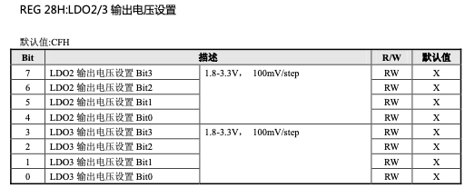
Whereas register 12H controls the state (ON/OFF) of a bunch of wires, including LDO2 (bit 2). Hence the code above.

-
Does your code cut the voltage to the backlight only? or to the screen as well?
-
To be tested but I think this turns off OLED_VDD, ie the current to the OLED. Register 10H is said to be for OLED_VPP so setting it to zero could help too.
-
I did a simple test: with only REG 28H the screen stays slightly warm. With both 28H and 10H, the screen cools off after a while. Hardly a scientific test, I know, but seems to point to the need to set both registers.
-
@dda what a wonderful work you have done! I hope this will enable @Multihelix to use M5StickC as a watch (turn off OLED after a timeout and turn on OLED on button press or accelerometer)
-
How are you getting 5 hours of life? it seems you would need <16 ma total drain
Are you sleeping the ESP32?
-
@ws1088 Funny enough I bought my M5StickC with the watch strap and all, but not because I wanted a watch – I don't wear them – but because it enables me to tie it up to my backpack when I do LoRa range tests :-)
-
@dda said in M5StickC: turn off screen completely:
@ws1088 Funny enough I bought my M5StickC with the watch strap and all, but not because I wanted a watch – I don't wear them – but because it enables me to tie it up to my backpack when I do LoRa range tests :-)
why would you use m5stickc to do LoRa range tests? You can get LoRa chip with OLED screen. Do you connect m5stickc to a LoRa chip via I2C? or WiFi AP?
-
I have a lot of different LoRa chips and setups. I have one board, at 230 MHz, that I can connect through the hat connector (I need 3 pins + Vcc/GND). I have transceivers, both at 230 and 433 MHz, I connect to via RS485 (I bought a hat for that, and also some RS485 for my M5Stack cores). etc etc. The smaller the better :-)
-
@maxstack - Yes, I used ESP DeepSleep set to wake on Button A being pressed, but I would say that the 5 hour time was not under ideal conditions, as I occasionally woke up the device to confirm it was still working and to check the time - a resonable activity for a watch.
-
@multihelix Can you post a link to your watch code?
-
@dda said in M5StickC: turn off screen completely:
I did a simple test: with only REG 28H the screen stays slightly warm. With both 28H and 10H, the screen cools off after a while. Hardly a scientific test, I know, but seems to point to the need to set both registers.
I'm looking at this thread to hopefully implement a complete screen turn off, but am not sure what register mask to use (based on quoted post)
Here is what I have, the screen is off but hard to know if the screen has actually been disabled.
void turnOffScreen() {
Wire1.beginTransmission(0x34);
Wire1.write(0x10);
Wire1.write(0b00000000); // 7-3=? | 2=EXTEN | 1=? | 0=DC-DC2
Wire1.endTransmission();Wire1.begin(21, 22);
Wire1.beginTransmission(0x34);
Wire1.write(0x12);
Wire1.write(0b01001011); // 7=? | 6=EXTEN | 5=? | 4=DC-DC2 | 3=LDO3 | 2=LDO2 | 1=DC-DC3 | 0=DC-DC1
Wire1.endTransmission();Wire1.beginTransmission(0x34);
Wire1.write(0x28);
Wire1.write(0b00001111); // 7-4=LDO2 | 3-0=LDO3
Wire1.endTransmission();
}
Hello! It looks like you're interested in this conversation, but you don't have an account yet.
Getting fed up of having to scroll through the same posts each visit? When you register for an account, you'll always come back to exactly where you were before, and choose to be notified of new replies (either via email, or push notification). You'll also be able to save bookmarks and upvote posts to show your appreciation to other community members.
With your input, this post could be even better 💗
Register Login