I poked around the APX192 code, and around a datasheet found here. First, there's this code:
void AXP192::begin(void) {
Wire1.begin(21, 22);
Wire1.beginTransmission(0x34);
Wire1.write(0x10);
Wire1.write(0xff); //OLED_VPP Enable
Wire1.endTransmission();
Wire1.beginTransmission(0x34);
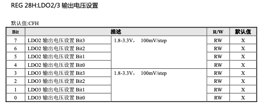
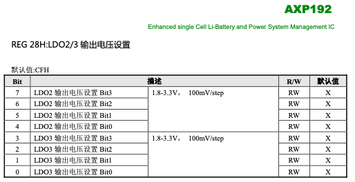
Wire1.write(0x28);
Wire1.write(0xff); //Enable LDO2&LDO3, LED&TFT 3.3V
Wire1.endTransmission();
A peek at the datasheet says that REG 28H is power management for LD02 and LD03. Sure thing. That's what the comment in the code above says – along with a hint that LD03 is for the TFT.
Meanwhile, REG 10H is two ON/OFF switches, for EXTEN and DC-DC2 – commented in the code as VPP_Enable. Bueno.
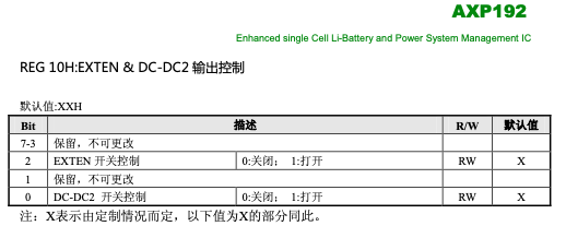
I am not sure which of EXTEN or DC-DC2 is connected to the OLED (both?), but turning either or both off will cut off the current to the OLED.
Moreover there's this code later:
  Wire1.beginTransmission(0x34);
  Wire1.write(0x12);
  Wire1.write(0x4d); //Enable DC-DC1, OLED_VDD, 5B V_EXT
  Wire1.endTransmission();
And REG 12H seems to do more of the same as 10H:
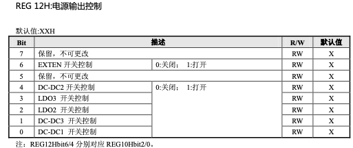
Bit 3 turns ON/OFF LD03, which, as we saw above, is supposed to be the OLED. Good odds that setting bit 3 of REG 12H to zero would work too.
I don't have time to test it now, but I'll try later tonight.