Reset Capacitor
-
@M5STACK ???
-
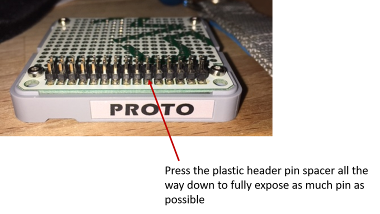
A couple of thoughts\suggestions for you. First, if you want to keep using the GND and RST on the base plate, your issue may be with the pins of the base plate (and\or any expansions) fully mating with the M-Bus header in the core unit. The plastic male header spacer on my base plate (as well as on a prototype and battery expansion) all were not fully seated. This basically shortened the pins and acted to limit the engagement of the pins with the Core MBus header and caused problems with the reset capacitor working as well as battery power feeding the Core board. The quick remedy that fixed that was to gently press the plastic space all the way down on the male pins. This appears to have given much better seating of the male pins into the female headers. See image:
-
With regard to a "permanent" capacitor, I think you have a few options. Cross check to the schematic on different ground points. That is located here: https://github.com/m5stack/M5-hardware/blob/master/M5_Core_SCH(20171206).pdf
My first thoughts for you are as follows:
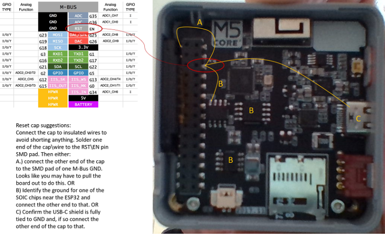
Please note that I have not dug into the SOIC chips to identify which pin is GND. I can't really make them out in your photo to identify which is which and correctly identify the ground pins that are candidates for the other connection. You'll need to check the chips and ID the ground pin or just go to the USB shield (after confirming it's tied to GND). you could possibly tie over to the grove header GND pin. Probably better to keep the capacitor whips (insulated wires I suggested) as short as possible and tie to either the MBus GND or one of the close SOIC's.
I am surprised that the shield was omitted on your board over the ESP32. It would be interesting to know if that is the case on all of that particular model. Can you advise if yours is the "newest" 2018 version with the PSRAM and IMU?
-
Needless to say, let us all know how you make out :) Also, the above should work but I'll warn you that I am a ME and can cause issues with EE stuff :)
-
@kentinker, the board is the latest with 4MB PSRAM and the MPU9250 or at least that's what I ordered. I am having so many issues with the reset button, the unit is almost unusable!
-
@pkourany - I feel your pain. I have pretty well isolated the issues with mine (Basic) to the pin and header connections for the MBus connecting the core (main) board with the sub-boards and base. After posting earlier, I actually took my bottom plate off and pulled the 850mah battery holder to check a few things related to some secondary circuits I am designing. I had fits getting everything to work again.
The stacking idea is a nice approach, but as an ME what I am seeing are tolerance issues with engagement of the male pins into the female sockets. I think there is a luck of the draw thing going on. There are mechanical tolerances on the pins and headers which will have variations from set to set. The same applies for the housings. Some of us just seem to have those at the extremes and end up with dicey header connections. The other compounding challenge tied to the pins seating is that all the male pin ends are tapered to help guide into the sockets - makes getting solid contact in the header all the more a variable thing.
I am in the process of looking at other ways to skin that particular cat and will let you know if I come up with something. Of course, one thing that helps me is that I have a different form factor in mind for how I want to integrate things and may be able to avoid. It's tough coming up with a stacking header system in such a small form factor as the M5Stack.
I think you will really like the device once you get past the issues you are having like some of the rest of us. It really is a nice setup and I am hoping that some of the growing pains and feedback work into better solutions for the next editions. Sucks a bit dropping the coin for one only to have to fuss with it to get some basic things to work.
JimiT noted that the manual states you may need to hold the power (red) butting in while flashing. Haven't tried that myself yet but that may be a short term option. If you get a clearer image of the board so I can read the SOIC chips, I'd help identify the ground points.
-
@kentinker, even without the bottom plate the M5Stack has reset problems. I believe this is related to a design flaw in the charger/power control circuit or in the chip itself. I really like the M5Stack but I have yet to see a valid solution to this problem.
As to why my M5Stack doesn’t have a shield around the ESP32, that would be for @m5stack to answer!
-
Unlike the earlier model M5Stack, the model with 4Mb PS-RAM and MPU9250 does not use a shield over the chip.
As per Windows install instructions at:
https://github.com/m5stack/M5Stack/blob/master/docs/arduino-ide/windows.md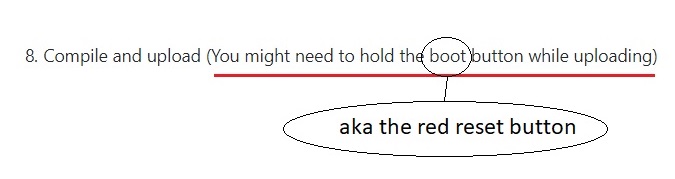
-
the psram version had changed to a big cap on the board, so it should not has the reset issue.
-
@m5stack, holding the button for programming works fine. Resetting is the issue with my unit. In some cases, even with the bottom plate off, the unit will not reset and run the downloaded firmware unless I let it sit a while. Other times it works fine.