M5Paper EPD power consumption
-
Hi guys
I just discovered that the voltage divider used to feed the battery voltage into the ADC uses different values from what's listed in the M5Paper schematic.
- M5Paper schematics: 3 kOhm and 11 kOhm -> factor: 0.78571428571
- found in my M5Paper: 10 kOhm and 10 kOhm -> factor: 0.5
With the actual values the modified SCALE factor (0.785.. -> 0.5) found in the library also makes more sense. It compensates the voltage divider.
BTW: when you feed 4.2 V into the original 3 kOhm / 11 kOhm voltage divider you get exactly 3.3 V. So I guess initially M5Paper was designed / planned to use a 4.2 V battery.
Cheers
Felix -
Hi guys
I think I found the reason for why the touch IC (GT911) did not react when I tried to put it into sleep mode. The procedure asks for the ESP32 GPIO used for the touch interrupt to change to an output and then be driven low by the ESP32. Unfortunately GPIO36 is used for the touch interrupt and that is one of the few GPIOs which can only be used as input. So without hardware modification I don't see a way to put the touch IC into sleep mode. Or am I missing something?
Thanks
Felix -
@felmue that definitely sounds like a massive design issue - I wonder, maybe that's why the M5EPD library doesn't have any touchscreen power-off calls?
There was also a post on the M5Stack twitter recently, showing a blurred out image of upcoming devices, with a device eerily similar to the M5Paper taking up a large chunk of the photo: https://twitter.com/M5Stack/status/1357559621389479940/photo/1
I wonder if the design team realised these small issues and made a new board that is more fit for general usage purposes. It happened with the M5Cores (the Basic model had no PSRAM and the first units only had 4MB storage, which later got expanded to 16MB, then the Grey kit came with an MPU, then the Fire kit also included a microphone and PSRAM, among other changes), though the speed is much faster - I think there was almost a year between the Basic and Grey M5Cores, whereas the M5Paper was only recently released.
It does feel like a slap in the face for us who already bought multiple M5Paper units though - we've received a device that has a handful of obvious faulty design choices, and now we have to buy the new, updated model to get functionality that should've been working in the first iteration. Don't get me wrong, I'm happy for the updated design, I just hope there will be some discount for those who've already got units on their hands.
-
You mention that you got the touch wakeup working. Could you share how you managed to do this?
I have searched and tried everything. I have had no luck with the touch wakeup. Currently my Homekit panel runs for about 5 hours without any sleep setup. This is just too low. I only need to use it couple of times a day and most of the time it should be on sleep.
-
Hi guys
I went ahead and modified my M5Paper so it can put the touch IC (GT911) into sleep mode. By doing so the current (measured at the battery) drops about 7.6 mA.
With WiFi off, EDP power off, ESP32 in deep sleep and touch in sleep mode the overall current is about 1.6 mA.
Note: since putting touch into sleep mode requires touch INT to be driven low by ESP32, touching the screen can no longer be used to wake up M5Paper.
Cheers
Felix -
@felmue
Indeed GPIO36 is only input.
So I looked for another GPIO used only as input to reverse the 2 GPIO on the pcb.
I found the GPIO27 which tells ESP32 that the IT8951 is ready for a SPI dialogueIT_SPI_HRDY (schema)
#define M5EPD_BUSY_PIN 27 (M5EPD.h)
EPD.begin(M5EPD_SCK_PIN, M5EPD_MOSI_PIN, M5EPD_MISO_PIN, M5EPD_CS_PIN, M5EPD_BUSY_PIN); (M5EPD.cpp)
m5epd_err_t M5EPD_Driver::begin(int8_t sck, int8_t mosi, int8_t miso, int8_t cs, int8_t busy, int8_t rst)
_pin_busy = busy;
pinMode(_pin_busy, INPUT);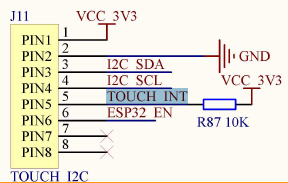
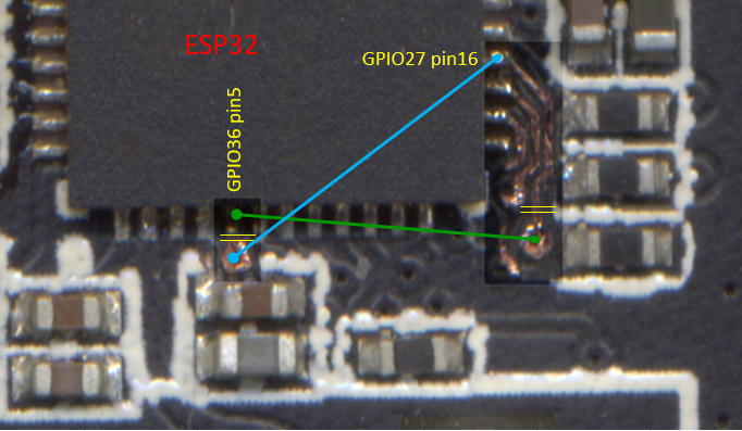
On my pcb, the resistance R87 is absent (unwelded)
All you have to do is reverse the 5 and 16 tabs on the ESP32.
I scraped the varnish and then scanned the pcb.
You have to cut the 2 tracks between the 2 pins of the esp32 and the 2 vias.
then solder 2 thin wires. -
-
Hello @bricox
very elegant solution. Thank you for sharing.
I opted to leave GPIO36 as is and connected GPIO19 (from port C) in parallel which I can then set to output if I want to use touch sleep mode. (Yes, I loose port C, but it made the soldering a bit easier. Only one additional wire from a pin on port C to the unpopulated R87 pad.)
Cheers
Felix -
@felmue
I did a summary of the 3 ports A, B and C
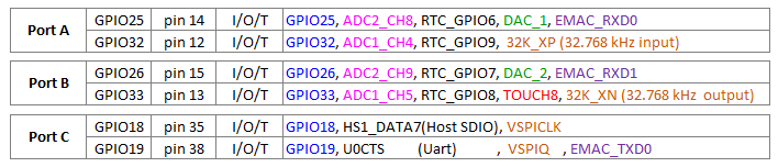
You made a good choice using GPIO19.
Indeed, welding work is simplified.
Do you share your source code? -
Hello @bricox
@bricox said in M5Paper EPD power consumption:
Do you share your source code?
Sure, you can find my touch sleep mode test sketch here.
It's a extended version of the TOUCH example which uses the left/up button to set touch into normal mode and right/down button to set into sleep mode.
Cheers
Felix -
@felmue
To fully understand the GT911 controller, download these 2 pdf
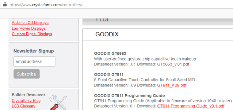
https://www.crystalfontz.com/controllers/GOODIX/GT911/464/
https://www.crystalfontz.com/controllers/GOODIX/GT911ProgrammingGuide/478/Several developments are desirable :
- read position under interrupt and not in polling mode [GT911::update()]
- Exploit more all modes
- Check if the "green mode" (3.3mA) automatically change after 1 second of inactivity
- Generate a sound when you touch it
List of 21 other GT911 drivers :
https://github.com/search?q=gt911
including one in cpp:
https://github.com/blackketter/GT911/blob/master/src/GT911.cpp -
@bricox based on the documentation, it should be possible to set the touch panel in a gesture recognising mode - would be nice to be able to offload that from the ESP32, alongside the interrupt-instead-of-poll change. This would certainly improve battery life.
-
-
Hello guys .... @felmue, @fonix232, @tatar-andrei... and other enthusiasts ....
I have others links for the GT911 driver in cpp
With interrupt : https://github.com/nik-sharky/arduino-goodix/blob/master/Goodix.cpp
No interrupt but handles 5 fingers : https://github.com/caiannello/ER-TFTM0784-1/blob/master/src/touch.cppWe’ll have to adapt these source codes.
Sorry, i'm not a specialist for interrupts of Arduino framework....I am more familiar with the HAL framework of the STM32.
Thank you for these sustained sharing
-
hello,
a little bit of electronics (because no present in official doc) :
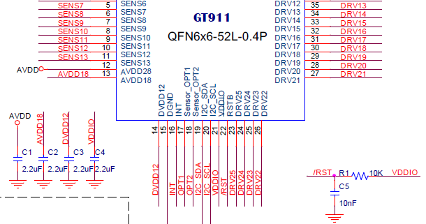
The PFL with C1, C2, C3, C4 R1 and C5:
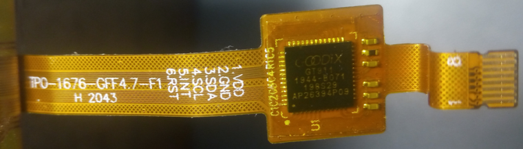
Remark : pin 7&8 are "shield" -
Hello @felmue
Find 1 output, to put low the INT signal of GT911, have another way possible ....
In the ESP pdf, I found this :
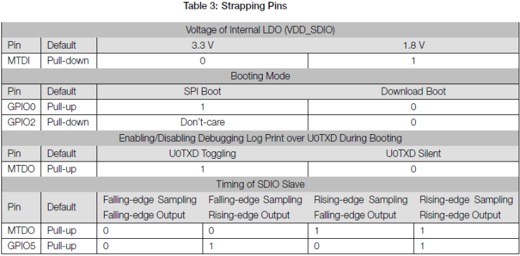
For reuse these pins, an article : https://www.instructables.com/ESP8266-Using-GPIO0-GPIO2-as-inputs/
I think that, in the M5paper, we can use GPIO0 as output.
What you think about ? -
Hello @bricox
in M5Paper GPIO0 (together with ESP32_EN) already is connected to the boot / download mechanism which is controlled by CP_RTS and CP_DTR from the USB chip. ESP32_EN is also connected to the touch reset line which together with the touch INT line determine which I2C address the touch IC is going to use.
If you also connect GPIO0 to the touch INT line, GPIO0 and ESP32_EN will not only determine the ESP32 boot mode but also the touch IC I2C address depending on what CP_RTS and CP_DTR are doing.
On the other hand controlling GPIO0 from code to put the touch IC into sleep mode might have a negative effect on the automatic boot / download mechanism.
I personally would leave GPIO0 alone, but in general it is correct that GPIO0 can be used as output if needed.
Thanks
Felix -
Hello @felmue,
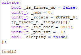
While I was commenting on the source code, I found un bug in the GT911 driver :
_fingers[]can be indexed up to 5
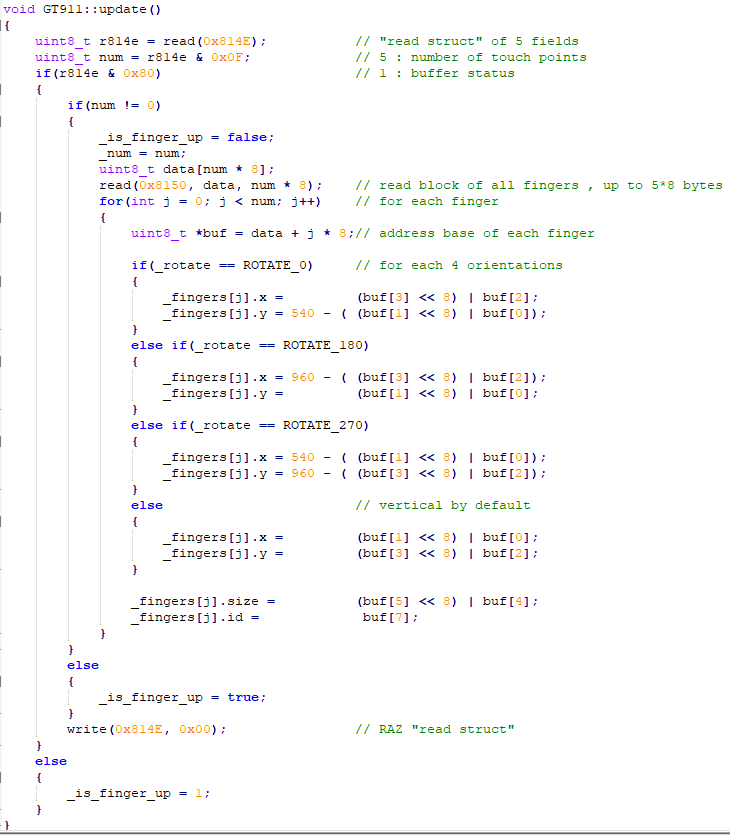
In declaration,_fingers[]can be indexed up to 2
In addition, it would be elegant to use bit fields for describing registers that have specific functions.
An example :
-
Structure
typedef struct reg814E_s {		//
 union {						// same location of 2 fields of 1 byte
   uint8_t reads;				// this byte
   struct {					// field bits of this byte
     uint8_t touchPts  : 4;	// b0 to b3 : number of touch points
     uint8_t haveKey   : 1;	// b4 : HaveKey
     uint8_t proxi     : 1;	// b5 : Proximity Valid
     uint8_t largeDet  : 1;	// b6 : large detect
     uint8_t status    : 1;	// b7 : buffer status
   };
 };
} __attribute__((packed)) reg814E_t;	// minimize memory alignment
or simpler writing
typedef struct {
  union {              // same location of 2 fields of 1 byte
    uint8_t reads;     // this byte
    struct {           // field bits of this byte, starting with low weight
      uint8_t
        touchPts  : 4, // b0 to b3 : number of touch points
        haveKey   : 1, // b4 : HaveKey
        proxi     : 1, // b5 : Proximity Valid
        largeDet  : 1, // b6 : large detect
        status    : 1; // b7 : buffer status
    };
  };
} reg814E_t;
Declarations
private: bool _is_finger_up = false; uint8_t _num = 0; uint8_t _rotate = ROTATE_0; tp_finger_t _fingers[2]; reg814E_t r814E; uint8_t _iic_addr = 0x14; uint8_t _pin_int = -1; bool _sleeping = false; }; -
Use :
void GT911::updateB()						// as update but modify by Bricox ...
{
    r814E.reads = read(0x814E);				// "read struct" AND these 5 explicite bits fields
    if(r814E.status)
    {
        if(r814E.touchPts != 0)
        {
            _is_finger_up = false;
            _num = r814E.touchPts;			// "_num" could be definitively replaced by "r814E.touchPts"
            uint8_t data[num * 8];
            read(0x8150, data, _num * 8);	// read block of all fingers , up to 5*8 bytes
            for(int j = 0; j < _num; j++)	// for each finger
            {
                uint8_t *buf = data + j * 8;// address base of each finger
Sorry, comments that were aligned, in my notepad++ by multiple Tabs, are no longer aligned in the snippets viewer
Hello! It looks like you're interested in this conversation, but you don't have an account yet.
Getting fed up of having to scroll through the same posts each visit? When you register for an account, you'll always come back to exactly where you were before, and choose to be notified of new replies (either via email, or push notification). You'll also be able to save bookmarks and upvote posts to show your appreciation to other community members.
With your input, this post could be even better 💗
Register Login