M5Paper EPD power consumption
-
Hi guys
I went ahead and modified my M5Paper so it can put the touch IC (GT911) into sleep mode. By doing so the current (measured at the battery) drops about 7.6 mA.
With WiFi off, EDP power off, ESP32 in deep sleep and touch in sleep mode the overall current is about 1.6 mA.
Note: since putting touch into sleep mode requires touch INT to be driven low by ESP32, touching the screen can no longer be used to wake up M5Paper.
Cheers
Felix -
@felmue
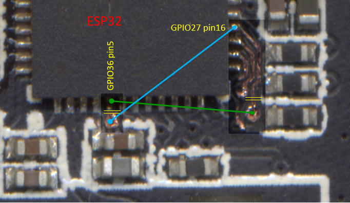
Indeed GPIO36 is only input.
So I looked for another GPIO used only as input to reverse the 2 GPIO on the pcb.
I found the GPIO27 which tells ESP32 that the IT8951 is ready for a SPI dialogueIT_SPI_HRDY (schema)
#define M5EPD_BUSY_PIN 27 (M5EPD.h)
EPD.begin(M5EPD_SCK_PIN, M5EPD_MOSI_PIN, M5EPD_MISO_PIN, M5EPD_CS_PIN, M5EPD_BUSY_PIN); (M5EPD.cpp)
m5epd_err_t M5EPD_Driver::begin(int8_t sck, int8_t mosi, int8_t miso, int8_t cs, int8_t busy, int8_t rst)
_pin_busy = busy;
pinMode(_pin_busy, INPUT);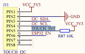
On my pcb, the resistance R87 is absent (unwelded)
All you have to do is reverse the 5 and 16 tabs on the ESP32.
I scraped the varnish and then scanned the pcb.
You have to cut the 2 tracks between the 2 pins of the esp32 and the 2 vias.
then solder 2 thin wires. -
-
Hello @bricox
very elegant solution. Thank you for sharing.
I opted to leave GPIO36 as is and connected GPIO19 (from port C) in parallel which I can then set to output if I want to use touch sleep mode. (Yes, I loose port C, but it made the soldering a bit easier. Only one additional wire from a pin on port C to the unpopulated R87 pad.)
Cheers
Felix -
@felmue
I did a summary of the 3 ports A, B and C
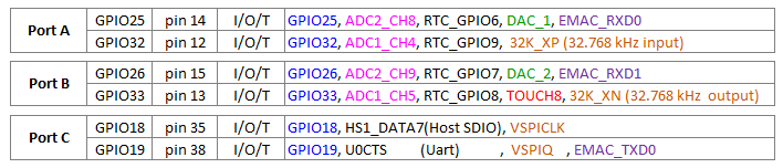
You made a good choice using GPIO19.
Indeed, welding work is simplified.
Do you share your source code? -
Hello @bricox
@bricox said in M5Paper EPD power consumption:
Do you share your source code?
Sure, you can find my touch sleep mode test sketch here.
It's a extended version of the TOUCH example which uses the left/up button to set touch into normal mode and right/down button to set into sleep mode.
Cheers
Felix -
@felmue
To fully understand the GT911 controller, download these 2 pdf
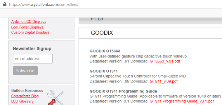
https://www.crystalfontz.com/controllers/GOODIX/GT911/464/
https://www.crystalfontz.com/controllers/GOODIX/GT911ProgrammingGuide/478/Several developments are desirable :
- read position under interrupt and not in polling mode [GT911::update()]
- Exploit more all modes
- Check if the "green mode" (3.3mA) automatically change after 1 second of inactivity
- Generate a sound when you touch it
List of 21 other GT911 drivers :
https://github.com/search?q=gt911
including one in cpp:
https://github.com/blackketter/GT911/blob/master/src/GT911.cpp -
@bricox based on the documentation, it should be possible to set the touch panel in a gesture recognising mode - would be nice to be able to offload that from the ESP32, alongside the interrupt-instead-of-poll change. This would certainly improve battery life.
-
-
Hello guys .... @felmue, @fonix232, @tatar-andrei... and other enthusiasts ....
I have others links for the GT911 driver in cpp
With interrupt : https://github.com/nik-sharky/arduino-goodix/blob/master/Goodix.cpp
No interrupt but handles 5 fingers : https://github.com/caiannello/ER-TFTM0784-1/blob/master/src/touch.cppWe’ll have to adapt these source codes.
Sorry, i'm not a specialist for interrupts of Arduino framework....I am more familiar with the HAL framework of the STM32.
Thank you for these sustained sharing
-
hello,
a little bit of electronics (because no present in official doc) :
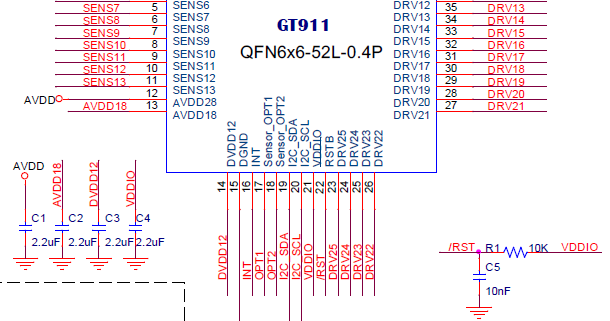
The PFL with C1, C2, C3, C4 R1 and C5:
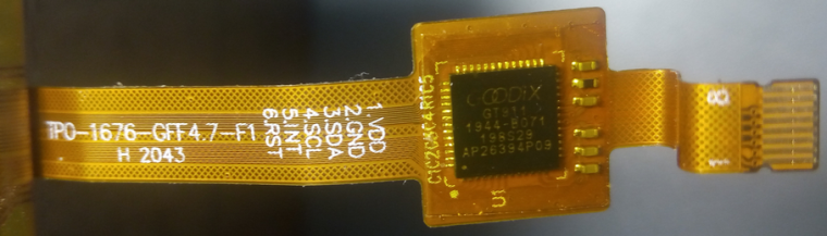
Remark : pin 7&8 are "shield" -
Hello @felmue
Find 1 output, to put low the INT signal of GT911, have another way possible ....
In the ESP pdf, I found this :
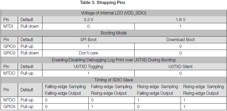
For reuse these pins, an article : https://www.instructables.com/ESP8266-Using-GPIO0-GPIO2-as-inputs/
I think that, in the M5paper, we can use GPIO0 as output.
What you think about ? -
Hello @bricox
in M5Paper GPIO0 (together with ESP32_EN) already is connected to the boot / download mechanism which is controlled by CP_RTS and CP_DTR from the USB chip. ESP32_EN is also connected to the touch reset line which together with the touch INT line determine which I2C address the touch IC is going to use.
If you also connect GPIO0 to the touch INT line, GPIO0 and ESP32_EN will not only determine the ESP32 boot mode but also the touch IC I2C address depending on what CP_RTS and CP_DTR are doing.
On the other hand controlling GPIO0 from code to put the touch IC into sleep mode might have a negative effect on the automatic boot / download mechanism.
I personally would leave GPIO0 alone, but in general it is correct that GPIO0 can be used as output if needed.
Thanks
Felix -
Hello @felmue,
While I was commenting on the source code, I found un bug in the GT911 driver :
_fingers[]can be indexed up to 5
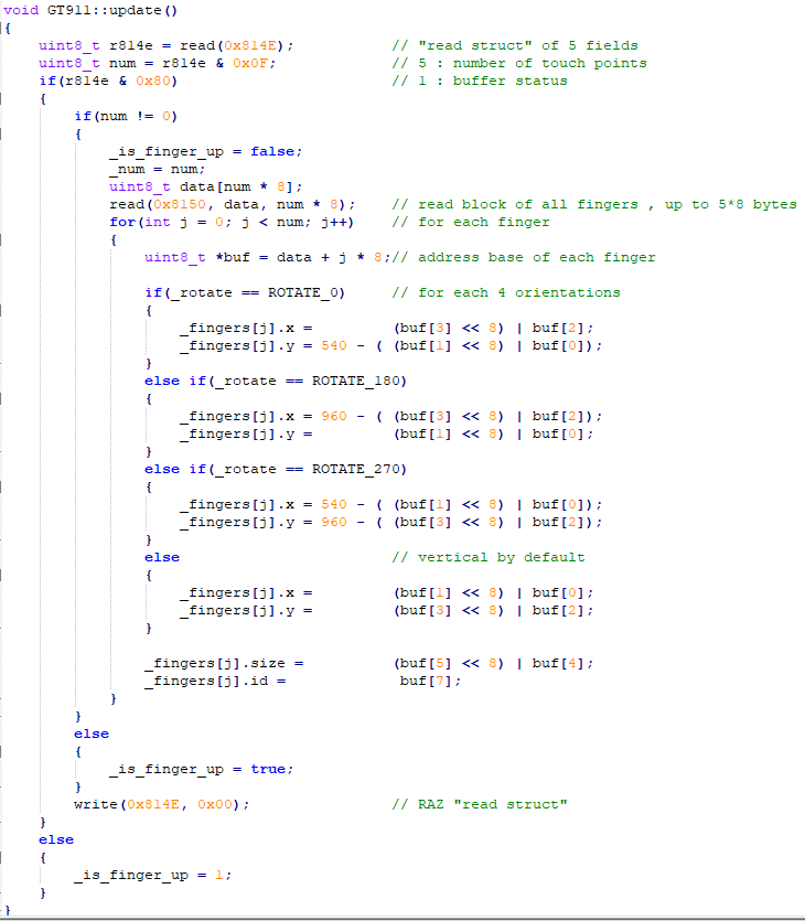
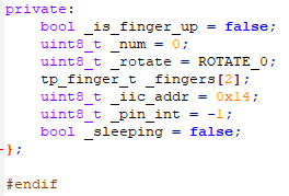
In declaration,_fingers[]can be indexed up to 2
In addition, it would be elegant to use bit fields for describing registers that have specific functions.
An example :
-
Structure
typedef struct reg814E_s {		//
 union {						// same location of 2 fields of 1 byte
   uint8_t reads;				// this byte
   struct {					// field bits of this byte
     uint8_t touchPts  : 4;	// b0 to b3 : number of touch points
     uint8_t haveKey   : 1;	// b4 : HaveKey
     uint8_t proxi     : 1;	// b5 : Proximity Valid
     uint8_t largeDet  : 1;	// b6 : large detect
     uint8_t status    : 1;	// b7 : buffer status
   };
 };
} __attribute__((packed)) reg814E_t;	// minimize memory alignment
or simpler writing
typedef struct {
  union {              // same location of 2 fields of 1 byte
    uint8_t reads;     // this byte
    struct {           // field bits of this byte, starting with low weight
      uint8_t
        touchPts  : 4, // b0 to b3 : number of touch points
        haveKey   : 1, // b4 : HaveKey
        proxi     : 1, // b5 : Proximity Valid
        largeDet  : 1, // b6 : large detect
        status    : 1; // b7 : buffer status
    };
  };
} reg814E_t;
Declarations
private: bool _is_finger_up = false; uint8_t _num = 0; uint8_t _rotate = ROTATE_0; tp_finger_t _fingers[2]; reg814E_t r814E; uint8_t _iic_addr = 0x14; uint8_t _pin_int = -1; bool _sleeping = false; }; -
Use :
void GT911::updateB()						// as update but modify by Bricox ...
{
    r814E.reads = read(0x814E);				// "read struct" AND these 5 explicite bits fields
    if(r814E.status)
    {
        if(r814E.touchPts != 0)
        {
            _is_finger_up = false;
            _num = r814E.touchPts;			// "_num" could be definitively replaced by "r814E.touchPts"
            uint8_t data[num * 8];
            read(0x8150, data, _num * 8);	// read block of all fingers , up to 5*8 bytes
            for(int j = 0; j < _num; j++)	// for each finger
            {
                uint8_t *buf = data + j * 8;// address base of each finger
Sorry, comments that were aligned, in my notepad++ by multiple Tabs, are no longer aligned in the snippets viewer
-
The power consumption you're observing on your M5Paper when the EPD (Electrophoretic Display) is idle is indeed higher than expected. It's unlikely that you have a defective unit, as the behavior you described is more likely related to software or driver optimization.
EPD displays typically have low power consumption because they require power only during screen updates. Once the image is displayed, the EPD consumes very little power to maintain the image. However, it's possible that the EPD driver or the default app on your M5Paper is not optimized for low power consumption during idle periods.
To optimize the EPD power consumption during idle periods, you could try the following steps:
Check for firmware updates: Ensure that you have the latest firmware version for your M5Paper. Manufacturers often release firmware updates that include optimizations and bug fixes that can improve power efficiency.
Look for power-saving options: Check if there are any power-saving options available in the EPD driver or the default app settings. Some devices offer options to reduce the refresh rate or enable power-saving modes for the EPD.
Consider customizing the EPD driver: If you have experience with programming and access to the EPD driver source code, you can explore the possibility of customizing the driver to optimize power consumption during idle periods. This might involve tweaking the refresh mechanism or implementing additional power-saving features.
It's worth noting that while EPD displays are generally power-efficient, power consumption can vary depending on factors like display size, color depth, and the specific implementation of the EPD driver. Therefore, it's not uncommon to encounter variations in power consumption between different devices or even different firmware versions.
-
The E-Ink Paper Display (EPD) on the M5Paper consumes power even when the screen is idle due to its underlying technology. E-Ink displays are different from traditional LCD or OLED screens in that they only consume power when the content on the screen is changed. Once an image or text is displayed on an E-Ink screen, it doesn't require any power to maintain that state. However, changing the content on the screen, such as refreshing to display a new image or text, does consume power.
In your case, when the EPD power is disabled, the display is essentially turned off, and it consumes very little to no power because it's not actively refreshing the content. When you enable the EPD power and the display is idle, it's likely in a state where it's ready to receive new content and is therefore consuming some power in anticipation of a refresh.
The power consumption you're observing is not necessarily a sign of a defective unit but rather a characteristic of E-Ink displays. If you want to optimize power consumption further for your low-power application, you might consider:
Reducing Refresh Rate: Minimize the frequency of screen refreshes. E-Ink displays are typically used in applications where the content doesn't change frequently. You can adjust the refresh rate to be as infrequent as possible to save power.
Full Screen Updates: Instead of partial screen updates, use full screen updates when you need to change the content. Partial updates can be more power-intensive.
Deep Sleep: Continue using the deep sleep mode of the ESP32 when the screen is idle. This will significantly reduce overall power consumption.
Optimize Code: Make sure your code is efficiently managing the display and other peripherals. Ensure that you are properly putting the ESP32 into deep sleep mode when it's not actively needed.
Hardware Modifications: Depending on your specific use case, you might consider hardware modifications to further reduce power consumption. This could involve custom power management circuitry or using different power supplies.
Hello! It looks like you're interested in this conversation, but you don't have an account yet.
Getting fed up of having to scroll through the same posts each visit? When you register for an account, you'll always come back to exactly where you were before, and choose to be notified of new replies (either via email, or push notification). You'll also be able to save bookmarks and upvote posts to show your appreciation to other community members.
With your input, this post could be even better 💗
Register Login