Where can I find examples of using UART module in UIFlow?
-
@felmue I tested my target device the PIN is 3.3V, so, I need to downgrade M5 from 5V to 3.3V? Many thanks!
-
@zhoubinx M5 gpio/ grove are 3.3v so if your device side is 3.3 then all good, be sure that tx goes to rx and rx to tx, same baudrate and parity ....
-
Hello @zhoubinx
like @robski already mentioned, you only need level shifter if your target board TX and RX pins are different from M5Stack Groove port, which uses 3.3 V on its data pins. (Only the red wire of the Groove port, providing power to the M5Stack units, is 5 V.)
Are you sure your target board uses 3.3 V on the data pins? Arduino boards (especially old ones) mostly use 5 V on their data pins.
Thanks
Felix -
 It looks like the bad thing is from AXP2101 power chip, all the PORTs were set to 5V? Please, any idea of how to lower voltage to 3.3V.
I will also find a multimeter to give a test. -
Hello @zhoubinx
I am not sure you fully understand the concept of how the Groove port of M5Stack devices are setup.
- Power (red wire) provides 5 V to M5Stack units (which if required turn the 5 V internally to 3.3 V using an DC/DC converter or LDO).
- Data lines (yellow and white wire) use 3.3 V
- GND (black wire)
In your case I assume the 3rd party device (Arduino) is already powered by its own power supply. If yes, then there is no need to use the power (red wire) of the M5Stack.
If the 3rd party device is using 3.3 V on its data lines (TX and RX) then the wiring is as follows:
M5Stack (3.3 V) TX <---> RX (3.3 V) of 3rd party device
M5Stack (3.3 V) RX <---> TX (3.3 V) of 3rd party device
M5Stack GND <---> GND of 3rd party deviceIf the 3rd party device is using 5 V on its data lines (Tx and RX) then the wiring is as follows:
M5Stack (3.3 V) TX <---> Level shifter <---> RX (5 V) of 3rd party device
M5Stack (3.3 V) RX <---> Level shifter <---> TX (5 V) of 3rd party device
M5Stack GND <---> GND of 3rd party deviceHere is an example M5Stack unit which uses an DC/DC converter to lower the 5 V to 3.3 V and includes level shifters for the data lines. See schematic.
Thanks
Felix -
@zhoubinx said in Where can I find examples of using UART module in UIFlow?:
It looks like the bad thing is from AXP2101 power chip, all the PORTs were set to 5V? Please, any idea of how to lower voltage to 3.3V.
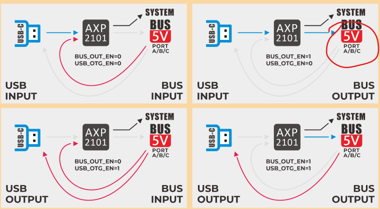
I will also find a multimeter to give a test.on your graphic USB-C is not PORT C (blue) - unfortunately it is drawn in blue - but this is USB port which you are connecting your Laptop /pc to M5Stack
in general on Ports A/B/C wires blk/red are power pins with gnd/5v on them where other two pins wht/yellow are data/sensor pins with 3.3v expected
-
Thanks all friends! I finally figure it out.
I think it is still related to AXP2101. When I keep the USB-C connected and use PORT C to communicate, it works. When plug off the USB-C, PORT C UART port just never send and receive data. I think it is because the USB-C supply power to the PORT C, not the inside battery. I will try to figure out how to let the battery to give power to PORT C. -
Hello @zhoubinx
I am glad to hear you got it working (at least with USB-C power).
BTW: My M5CoreS3 (running UIFlow2 firmware) provides power to all Groove ports (A/B/C) in both cases: running from USB-C or battery.
In your hardware setup, what do you need the 5 V of the Groove port for? If you have a multimeter it should be relatively easy to verify 5 V being present or not.
Thanks
Felix -
Hi guys
I've created an UIFlow2 example (M5CoreS3_Ext_Usb_Power_UIFlow2.0.1) showcasing switching ext. power output (Groove port) and USB power output. You can find it in the UIFlow2 Play Zone.
Thanks
Felix -
Thanks Felix! I will study your new example.
Hello! It looks like you're interested in this conversation, but you don't have an account yet.
Getting fed up of having to scroll through the same posts each visit? When you register for an account, you'll always come back to exactly where you were before, and choose to be notified of new replies (either via email, or push notification). You'll also be able to save bookmarks and upvote posts to show your appreciation to other community members.
With your input, this post could be even better 💗
Register Login