M5 Dial Port B both Pins needed to be outputs
-
I am trying to use Port B (Black Port) G1 and G2 as PWM and direction outputs
Both UIflow 2.0.3 and arduino don't seem to make Pin 2 as output but no warnings
I have read the documentation of S3 and I see no reason that both pins cannot be outputs
I know on Tough one of the pins could only be input but i see no reason for this on s3
What am i missing -
Hello @ToughBJH
in UIFlow2.0.4 after enabling PWM hardware I can add two Init Pin blocks, one for GPIO1 and one for GPIO2, set duty values for each and using a multi-meter I can confirm that both output the respective voltage.
Thanks
Felix -
@felmue
Thanks
I find that pin 2 follows pin 1 with scope
try setting the duty cycle of pin 1 and watch pin 2
setting duty cycle of pin 2 does nothing
simpler test
put led load with 330 ohm resistor on each pin and timer for each at different times
pin 2 led never lights but on scope it toggles 0- -3.3 volts
I have 2 units and both do this is something wrong in the pin map set with idf? -
Hello @ToughBJH
that is not what I am seeing. Please have a look at the UIFlow ProjectZone example M5Dial_PWM_GPIO1_GPIO2_UIFlow2.0.4.
It controls GPIO1 and GPIO2 independently. I verified it with the multi-meter and two LEDs (plus resistor).
Thanks
Felix -
@felmue
I tried your program thanks
i changed pin 1 23-400 and 400 - 23
and both pins follow pin 1I erased and burned 2.0.4 hotfix twice
I checked it with thonny and it says its still at 2.0.3
MPY: soft reboot_ __ __ ()/ | | _____ __
| | | | | || |/ _ \ \ /\ / /
| || | | | | () \ V V /
_,||| ||___/ _/_/ 2.0.3[INFO] Syncing resources...
[WARN] WiFi not connected.
[WARN] quit sync.
MicroPython v1.22.0-dirty on 2024-04-16; M5STACK Dial with ESP32-S3-FN8Type "help()" for more information.
-
Hello @ToughBJH
I tested with v2.0.3 and v.2.0.4--hotfix firmware and with either firmware GPIO1 and GPIO2 act independently.
BTW: v2.0.3 firmware has been built on 2024-03-21 whereas firmware v2.0.4--hotix has been built on 2024-04-16. The fact that both report 2.0.3 is probably just an oversight.
Not sure where to go from here. I'd say your M5Dial might have a hardware issue, but since your seeing it on both your M5Dials that seems a bit far fetched.
At this point in time I am out of ideas, sorry.
Thanks
FelixGPIO translation table M5Stack / M5Core2
Information about various M5Stack products.
Examples -
If you can’t change pin 2 to output then it’s set in hardware or deep in the firmware. All port B devices have 1 input and 1 output don’t mess with the definition. If you need more they try a port b hub or I/o expander
-
@felmue
Thanks for your reply's
I am thinking- Buy a m5stamp s3 and try that
- Wait for new batch of dials buy one see if thats different
- Figure out how to use the idf (not likely)
Thanks for getting back to me so quickly
-
@felmue I have been following this issue for a week or so and trying to figure it out.
I see three things in the documentation that don't make sense, both Dial and DIN Meter.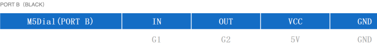
I still have the cute Demo sketches running and have not tried this myself, but it looks confusing?
-
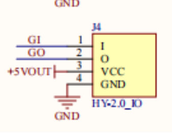
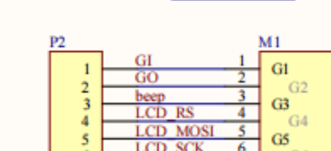
Hello @teastain
do you mean the GI (capital I for In) and GO (capital O for Out)?
That said, I think the strict one input and one output on port B is coming from ESP32 cores which would use one GPIO that actually only can be an input.
However the S3 variant doesn't seem to have this limitation anymore.
As I reported before I can set GPIO1 and GPIO2 of my M5Dial both to outputs and use them just fine.
And even if one or both of them are set as input in UIFlow firmware that should not prevent one from changing that in the user program. (Unless it is set as an input repeatedly in the UIFlow firmware.)
Note: I have not tested the same (both outputs) with an Arduino program.
Thanks
FelixGPIO translation table M5Stack / M5Core2
Information about various M5Stack products.
Examples -
@felmue Yes! That's it!
GI vs G1!!!
Thanks. -
@felmue
Followup
I discovered this problem is only if you are using pins in source mode.
In sink mode they behave as you said.
My bad thanks for your help
Hello! It looks like you're interested in this conversation, but you don't have an account yet.
Getting fed up of having to scroll through the same posts each visit? When you register for an account, you'll always come back to exactly where you were before, and choose to be notified of new replies (either via email, or push notification). You'll also be able to save bookmarks and upvote posts to show your appreciation to other community members.
With your input, this post could be even better 💗
Register Login