@hanktttop OK. I'm wading into this discussion without having a Cardputer!
My other ESP32-S3 and M5Stack Atom S3 and several StampS3s all work very well in my Arduino IDE environment. I also have a bunch of S3 products from a manufacturer whose name cannot be said. (coughs into hand...T-Display S3).
So I am familiar with this S3 series on a M1 iMac.
My iMac has two Thunderbolt ports and two USB ports. I used the USB ports just fine for M5Stack-pre-S3-models, but the S3 models wont even power up on USB, they need the Thunderbolt outputs.
So, get to the point, teastain.
Connection is VERY fussy and unpredictable with S3.
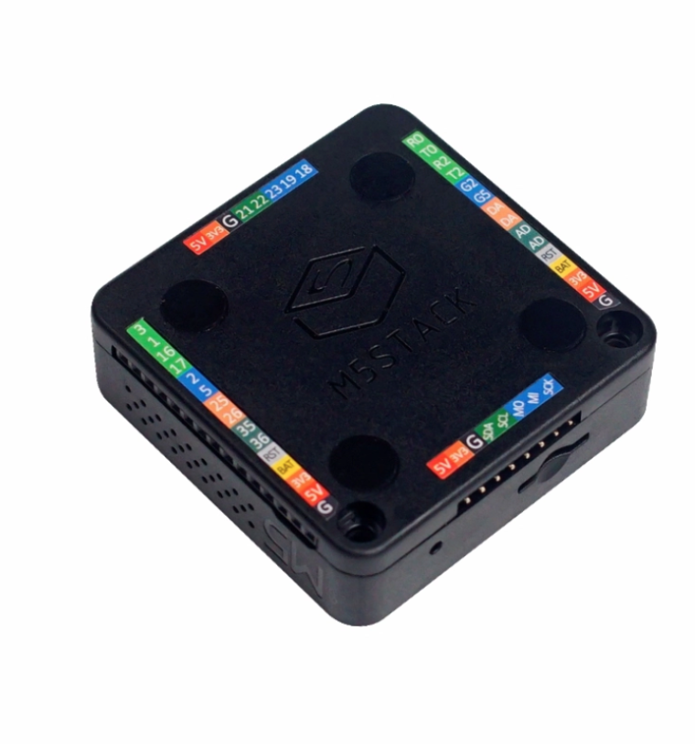
All of the M5Stack S3 products that I have seen have both of the necessary buttons available. The Cardputer even has them at the front(!) no need to remove the S3 or peel back the sticker on Cardputer. (in fact DO NOT remove the S3 with Cardputer!)
The GO button is actually GPIO 0 and is called 'boot'.
The 'rst' button is otherwise called 'EN' which cuts power to the core when pushed and resets when released.
Method 1 unplug the Cardputer from the USB, press and hold G0 (on the left side of the Cardputer, plug back in and release G0.
Method 2 while plugged in press and hold G0, press 'rst' on the right side, release 'rst', then release G0.
In both cases if your sketch does not boot up and run, it is recommended to unplug it and plug it back in to boot.
teastain
@teastain
Retired Industrial Robotics interface designer, bon vivant, raconteur, maker.
Best posts made by teastain
-
RE: Cardputer COM Not Working
-
RE: Connecting M5stack to PCB with header and GPIO capacity.
@mtylerjr The Core Basic has 15 GPIO peripherally arranged in the battery base, as well as generous grounds and voltage options.
-
RE: Looking for kind souls to adopt this aged brain and eyes.
@ajb2k3 I really like the idea of REPL !
MY(!) aging brain is resisting learning a new programming language.
In the (late) 70's I programmed in machine code and felt C was a "high level language".
I will investigate Python, could be fun!
Cheers to all.
-
RE: How to change the I2C address of EXT.IO2
@felmue "For testing integrity" I'm using the github EXT.IO Zip download and running the DIGITAL_INPUT_OUTPUT example right from there and then later from my Arduino directory, after checking that both Libraries M5Stack And EXT_IO are up to date.
Note, stubbornly I am using Arduino 1.8.19.
The Example would not run until I added Wire.begin(21, 22); delay(1000);
Seriously. I take it out and the sketch throws errors.
I am also disappointed that setPinMode "came and went".
I am becoming discouraged with M5Stack, unfortunately. -
RE: UnitCamS3 Trouble programming in Arduino IDE and getting 2mp image
@ajb2k3 Sure, here it is:
Here is the full example for all ESP32s using the OV2640 camera in Arduino IDE
(in the IDE board selection choose M5Stack UnitCamS3)
Remember to edit the .ino file to include your WiFi credentials!The full sketch is here:
https://github.com/espressif/arduino-esp32/tree/cf448906b3836fbe9368934713b697469254c62f/libraries/ESP32/examples/Camera/CameraWebServerYou can choose CAMERA_MODEL_ESP_EYE, and apply a little tweak in camera_pins.h like this:
https://github.com/m5stack/UnitCamS3-UserDemo/blob/main/firmware/src/hal/cam/camera_pins.h#L21Also in the library used in your sketch
app_httpd.cpp
I had to change Line 77 from ('1" enabled) to ('0' not enabled )#define CONFIG_LED_ILLUMINATOR_ENABLED 0
Successful upload serial output reads like this:
20:48:24.952 -> E (516) esp_core_dump_flash: No core dump partition found! 20:48:24.952 -> 20:48:24.952 -> ...... 20:48:24.952 -> WiFi connected 20:48:24.952 -> Camera Ready! Use 'http://192.168.0.37' to connect
-
RE: High Level Question regarding M5Stamp and Core2
Hi, I have a Core Basic HVAC program communicating with two Stamps using ESP_NOW and they are physically close, but the idea was to not run messy cables! The ESP_NOW is peer to peer WiFi, but no login to the internet or even the WiFi router.
One Stamp reads the HVAC vent temperature and reports to the Core, which in turn calculates the damper vane angle and transmits that back to the very same Stamp connected to a 180 servo motor.
The other Stamp just operates one or two small under desk heaters as required, by the Core.
Hope this helps.
Terry -
RE: M5cardputer com is reading it as DFROBOT-Beetle
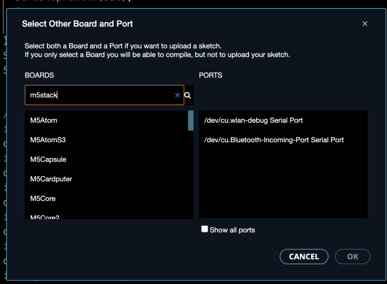
@coolman626 This is sadly a confusing aspect of Arduino IDE V2...a "feature" that guesses your board as a "convenience" and it's always wrong.
In the search box start typing M5Stack until you see your board!
Really no big deal!
-Terry -
RE: The other M5Dial connectors...
@lordryck They are called Grove and are the standard for most M5Stack products.
https://shop.m5stack.com/pages/search-results-page?q=grove cable
Also used by Seeed products.
They're JST connectors type 'HY2.0-4P'.
-
RE: m5stack cardputer doesn't turn on.
@sl4sh00 To put it into 'download' mode you can do as @robski suggested or:
Press and hold the G0 Boot button...while holding it in, press and release the reset button, THEN release the G0 Boot.
While doing this you can check the connection status in whatever burner app you are using.
Please tell us if you can see the connection status AT ALL, this would be helpful in solving your problem.
Latest posts made by teastain
-
RE: M5stack new joystick example
@YigalB Two Joysticks would require a PaHub accessory from M5Stack:
https://shop.m5stack.com/products/i2c-hub-1-to-6-expansion-unit-pca9548apw
These work very well, seamlessly.
I don't know how to change the I2C address of the Joystick in this register, sorry. -
RE: M5stack new joystick example
@YigalB I2C is correct.
Here is the example:
https://github.com/m5stack/M5Unit-Joystick2/blob/main/examples/get_value/get_value.ino
The internal firmware is already installed and like most M5Stack Units it is 'permanent' and does not require your attention but could theoretically be updated in the future. -
RE: How to get started With the m5stickc plus 2
@Bertibert No, we will not help you be a jerk.
Using this firmware for these activities would be illegal. -
RE: GROVE2GROVE and 5V DC fan
@l-roca It's your choice. If the load is within the 5V current output of the Dial, (which is 1000mA) then all you need is a M5Stack splitter (T-connector).
https://shop.m5stack.com/products/grove-t-connector-5pcs-a-pack
I just confirmed that now.
-
RE: GROVE2GROVE and 5V DC fan
@l-roca With Felix's help I got the power on/off working on an AtomS3, which is a 'kissing cousin' to the Dial. I have not yet got the Imeasure working, maybe today!?
If you are interested in my Arduino IDE sketch, contact me by email:
teastain@me.com -
RE: GROVE2GROVE and 5V DC fan
@felmue Thanks! Works perfectly. I too found R0 not connected/installed. My mistake was low side switching, whereby I had the LED upstream.
Your technique and explanation was perfect!
My complaint with M5Stack is they did not show the external hookup. pwr supply, load at all. You diagram made it work. -
RE: GROVE2GROVE and 5V DC fan
@l-roca Oh, sorry I only know Arduino IDE.
Having said that, I can't get it working right now for some reason.
There is a UIFlow version here:
https://docs.m5stack.com/en/unit/unit_grove2grove
at the very bottom of the page. -
RE: GROVE2GROVE and 5V DC fan
@l-roca Are you referring to Unit 148?
What are you going to control/measure?
What is the controller, i/e. Core? Atom, etc.?
What program do you use for downloading? -
RE: MOSFET unit
@felmue What an undiscovered gem, until I realized that I have one, way in the bottom of my parts drawer!
I did not realize that it would source 1A !!!
I just built a MOSFET inside a M5Stack Proto Unit to drive a display. duh -
RE: Simple Example of ESP-NOW Communication Between StickC Plus and M5Core Basic
I wrote this VERY terse, simplistic code to demonstrate ESP-NOW. You simply copy this code to an empty Arduino IDE sketch and change the particulars: I.e. Mac address LED pin and Button pin
Both M5Stack units, regardless of type use the same code except for the particulars, especially the MAC address. The demo sends a boolean single bit signal when its button is pressed and the other receives it and turns on its LED: You can easily convert it to send and receive an int or a float, whatever! It was written for two StickC Plus, but any ESP32 will do.#include <Arduino.h> #include <esp_now.h> #include <WiFi.h> #define LED 10 // or whatever you have #define Button 37 //Below is the address of the other unit uint8_t broadcastAddress[] = { 0x94, 0xB9, 0x7E, 0x8C, 0x7C, 0xE8 }; String success; typedef struct struct_message { bool State; } struct_message; // Create a struct_message to hold outgoing button struct_message TxButton; // Create a struct_message to hold incoming button (to turn on this LED) struct_message RxButton; //I.E. = incomingReadings // Register peer esp_now_peer_info_t peerInfo; void setup() { Serial.begin(115200); pinMode(LED, OUTPUT); digitalWrite(LED, HIGH); pinMode(Button, INPUT); WiFi.mode(WIFI_STA); // Init ESP-NOW if (esp_now_init() != ESP_OK) { Serial.println("Error initializing ESP-NOW"); return; } // get the status of Trasnmitted packet esp_now_register_send_cb(OnDataSent); memcpy(peerInfo.peer_addr, broadcastAddress, 6); peerInfo.channel = 0; peerInfo.encrypt = false; // Add peer if (esp_now_add_peer(&peerInfo) != ESP_OK) { Serial.println("A- Failed to add peer"); return; } // Register for a callback function that will be called when data is received esp_now_register_recv_cb(OnDataRecv); delay(1000); } void loop() { TxButton.State = digitalRead(Button); //***this is where you tramsmit this units button state esp_err_t result = esp_now_send(broadcastAddress, (uint8_t *)&TxButton, sizeof(TxButton)); if (result == ESP_OK) { Serial.println("Sent with success"); } else { Serial.println("Error sending the data"); } delay(500); } // OnDataRecv when data is received, LED is controlled here void OnDataRecv(const uint8_t *mac, const uint8_t *incomingData, int len) { memcpy(&RxButton, incomingData, sizeof(RxButton)); Serial.print("Bytes received: "); Serial.println(len); digitalWrite(LED, RxButton.State); //***this is where you receive the state of the other unit's button } void OnDataSent(const uint8_t *mac_addr, esp_now_send_status_t status) { Serial.print("\r\nA- Last Packet Send Status:\t"); Serial.println(status == ESP_NOW_SEND_SUCCESS ? "Delivery Success" : "Delivery Fail"); if (status == 0) { success = "Delivery Success :)"; } else { success = "Delivery Fail :("; } }