Tab5 error in schematic? or in block diagrams? Camera MCLK is not connected?
-
Hi. I've been looking at the Tab5 Schematics a lot recently. And noticed something that appears 'wrong'.
In the block diagrams the camera modules
CAM_MCLKline is shown as coming from pin G36 of the esp32-p4.
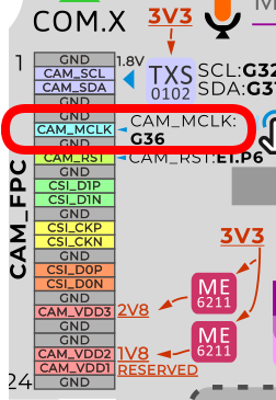
But the schematic tells a different story;
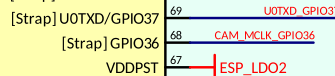
On the ESP32-P4 we have
CAM_MCLK_GPIO36coming from the esp32-p4:
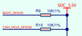
It has a 10K pullup (
R10) toSOC_3.3V:
But then is not used!
There are two
N/C(Not Connected) resistors (R27&R109) on the connection toU35(which drives the camera modulesCAM_MCLK_1V8at 1.8v)
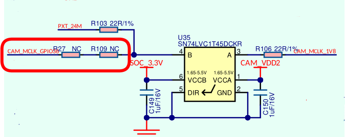
But note that the connection shown as
PXT24Mis connected, and comes fromX2, a 24 MHz CMOS crystal oscillator.Which is correct? The Schematic or the block diagrams?
If setting up a camera driver on the Tab5 can we safely ignore setting up
gpio36and just assume the cameraMCLKis permanently fixed at 24MHz?Edit: This isnt a criticism, it's quite normal; The board was designed so that it can accommodate two different camera module units. And the decision about which one to use can then be made closer to production time. Circuit designers do this a lot; the appropriate components are added/removed at production time without the PCB layout needing to be changed.
-
Hello @easytarget
from what I can tell the schematic is correct.
In the source code for M5Tab5-UserDemo
GPIO36is initialized as clock (see here).But when I modify function
bsp_cam_osc_init()to immediately return (so that the clock setup code is not executed) the camera still works fine.Thanks
FelixGPIO translation table M5Stack / M5Core2
Information about various M5Stack products.
Examples -
@felmue Thank you for doing the test :-)
I guess this simplifies things for anybody writing a driver; but does prevent people having fun-and-games with under/over clocking the camera module.
I think it also means you cannot 'stop' the camera, which may be problem for extreme power saving. But I suspect the reset pin can be used to halt the module too.
Hello! It looks like you're interested in this conversation, but you don't have an account yet.
Getting fed up of having to scroll through the same posts each visit? When you register for an account, you'll always come back to exactly where you were before, and choose to be notified of new replies (either via email, or push notification). You'll also be able to save bookmarks and upvote posts to show your appreciation to other community members.
With your input, this post could be even better 💗
Register Login