ATOMFLY Community Project Collection: How to fly the ATOMFLY?
-
Thanks for creating the thread. I understand this doesn't have a demo code but curious to know if this was ever flown by dev team? Maybe the stablity needs working on but does it lift off?
-
I asked in a tweet that why the Atom Lite reboots when the PWM value is increased above 95 or 100 for all motors. I got a reply from @m5stack: "I think the voltage drops too much, could u add one more cap between 3.3v and gnd. 100uf should be better." Before soldering a capacitor (100uf) I just wanted to make sure if it is 3.3V and GND. It is not clear from the schematics that Atom Lite is getting power from 5V or 3.3V? Please confirm.
-
AtomFly is based on Atom Lite which is new to me (I only have a M5Stack in the family)
I followed the document to install Arduino IDE and the library.
It was not clear but I figured out to install FastLed and ADThen I wanted to have a rough try to know if everything is ok and I picked few lines from the piece of code provided.
But:In file included from /home/titi/Arduino/libraries/FastLED/FastLED.h:65:0, from /home/titi/Arduino/libraries/M5Atom/src/utility/LED_Display.h:4, from /home/titi/Arduino/libraries/M5Atom/src/utility/LED_DisPlay.cpp:1: /home/titi/Arduino/libraries/FastLED/fastspi.h:130:23: note: #pragma message: No hardware SPI pins defined. All SPI access will default to bitbanged output # pragma message "No hardware SPI pins defined. All SPI access will default to bitbanged output"FastLed library has different implementation but only one with FastLed as complete name.
I'm using M5Stick-C as board target as mentionned in the doc.Any clue ?
Edit:
It is not obvious, it's been a while since I used Arduino IDE, it seems it's a warning, I was able to run through all motor tests.
So, for anyone looking at this, you can code and it works. -
@titimoby I got the same warning and ignored it for the moment. Yes, use M5Stick-C as board target. The led and motor tests work.
-
@yokonav strange, I haven't seen this problem, yet. Just measured the volts on the atom fly base pins, 5V pin and around 5v but 3.3v pin is 0, so it seems atom lite getting power from 5v.
-
I just received my atom fly and already did some tests since yesterday evening. I used the "AtomFly" sample code and looked into the accelerometer data to implement a PID control loop. Idea is to calculate pitch and roll values and come up with pwm values for the ESCs/motors to balance the drone to keep it flat. For example, if the drone is tilted left, the left two motors (A and C) will need more power and right two motors (B and D) will need less power.
It was my first attempt (and first ever coding any drone) but quickly got some initial code to try. So without the motors running, I got the PID results somewhat expected, good enough for the first draft code. Then holding under the atom fly, I "turned on" the motors and watched the accelerometer readings, pitch and roll values. The moment I turn on the motors, the accelerometer readings almost turns into random values. It's noise but the amplitude of the noise is quite shocking.
I tried a few methods to reduce noise, including averaging 10 reads from accelerometer, a low pass filter, but the not able to get a meangingful noise reduction. Here are the example pitch and roll values, while I was holding it exactly in the same position look at the values jump all over the place:
motors off
p 0.08 r 0.76
p 0.18 r 0.85
p 0.11 r 0.90
p 0.14 r 0.89
p 0.14 r 1.01
p 0.12 r 1.03
p 0.17 r 0.93
p 0.19 r 0.98
p 0.24 r 1.01
p 0.21 r 0.97
p 0.10 r 0.99
p 0.21 r 1.04
p 0.25 r 1.01
p 0.29 r 1.05
p 0.20 r 1.01
p 0.28 r 0.98
p 0.32 r 0.96
p 0.50 r 1.01
p -0.11 r 1.69
p 0.29 r 0.84
p 0.64 r 1.03
p 0.47 r 0.43
p 0.57 r 0.39
p 0.91 r 0.31motors on
p 1.52 r -0.21
p 2.13 r 0.42
p -1.55 r 0.93
p -4.36 r -3.68
p -7.84 r -8.67
p 10.32 r 18.60
p -12.92 r 9.18
p 10.58 r 35.11
p 14.80 r 13.29
p 14.80 r 30.15
p -7.86 r 10.19
p -10.08 r 5.31
p -29.28 r -11.35
p -43.59 r -19.16
p -18.37 r -1.91
p 7.71 r -13.85
p -9.24 r 8.91
p 19.41 r 4.72
p 24.34 r -4.03
p 17.54 r 27.78
p 19.21 r 12.25
p -11.16 r -9.75
p -24.23 r 1.72
p -26.27 r 29.51
p -33.18 r 15.28
p -14.21 r -10.03
p -9.11 r -0.97
p -10.81 r 35.41
p -4.66 r 0.96Is this level of noise common for accelerometers on a drone? Any input is welcome.
-
If anyone is interested, my draft code with PID control is now here: https://github.com/kaisarh/atomfly
Example of more noise data is here: https://github.com/kaisarh/atomfly/tree/master/noise_data
-
@roboticbits
Can you try following inside loop() and see if Atom Lite reboots?
fly.WritePWM(AtomFly::kMotor_A, 110);
fly.WritePWM(AtomFly::kMotor_B, 110);
fly.WritePWM(AtomFly::kMotor_C, 110);
fly.WritePWM(AtomFly::kMotor_D, 110); -
@yokonav Good point, do you know what's the valid range for the pwm values? I assumed it's up to 100 as %.
void ledcWrite(uint8_t chan, uint32_t duty)
{
if(chan > 15) {
return;
}
uint8_t group=(chan/8), channel=(chan%8);
LEDC_MUTEX_LOCK();
LEDC_CHAN(group, channel).duty.duty = duty << 4;//25 bit (21.4)Looking at the last line above, duty is multiplied by 16. These could be microseconds?
100 x 16 = 1,600 (us?)
110 x 16 = 1760 (us?)
131 x 16 = 2096 (us?)@m5stack Could you clarify the valid pwm value range?
-
@roboticbits said in ATOMFLY Community Project Collection: How to fly the ATOMFLY?:
ledcWrite
I think ledcSetup(0, 10000, 8); sets up channel 0 to 10KHz and 8-bit duty resolution so the range should be 0-255.
-
@roboticbits m5Stack replied me on Twitter: https://twitter.com/M5Stack/status/1295308095690649601
I am still confused it is 5V or 3.3V as you checked there is no power input from 3.3V. -
@yokonav Mine didn't have power at 3.3v pin, so it's confusing without investigating further.
To further check the atom reset issue, how about you use dupont cable to take the 9 pins out to a breadboard, then connect the atom lite from breadboard. In that way you can check the volts, volt drops, amps when fly base and atom lite is connected (and motors on). You can also add the 100uf cap in between power (3.3v or 5v) and gnd.
It's bit tricky and messy setup but will give you clues.
-
@yokonav Just tried upto 150 in all motors, it didn't reset (but I got a chipped nail, my fault). So there seems to be some variation in the reset behaviour.
-
@roboticbits take care of your safety first. Initially I also got a hit from props on my finger since then I tied it to a stick: https://twitter.com/knaveen/status/1293777343341711360
I will try to use a breadboard if it works.
-
@yokonav thanks, following your idea I'm also using sticks now.
-
I did some more tests and analysis of the noise and have some updates.
I re-wrote getAttitude() function and MPU6886 reading seem to have improved. I have a bunch of more sample data and analysis in noise_data folder (in github).
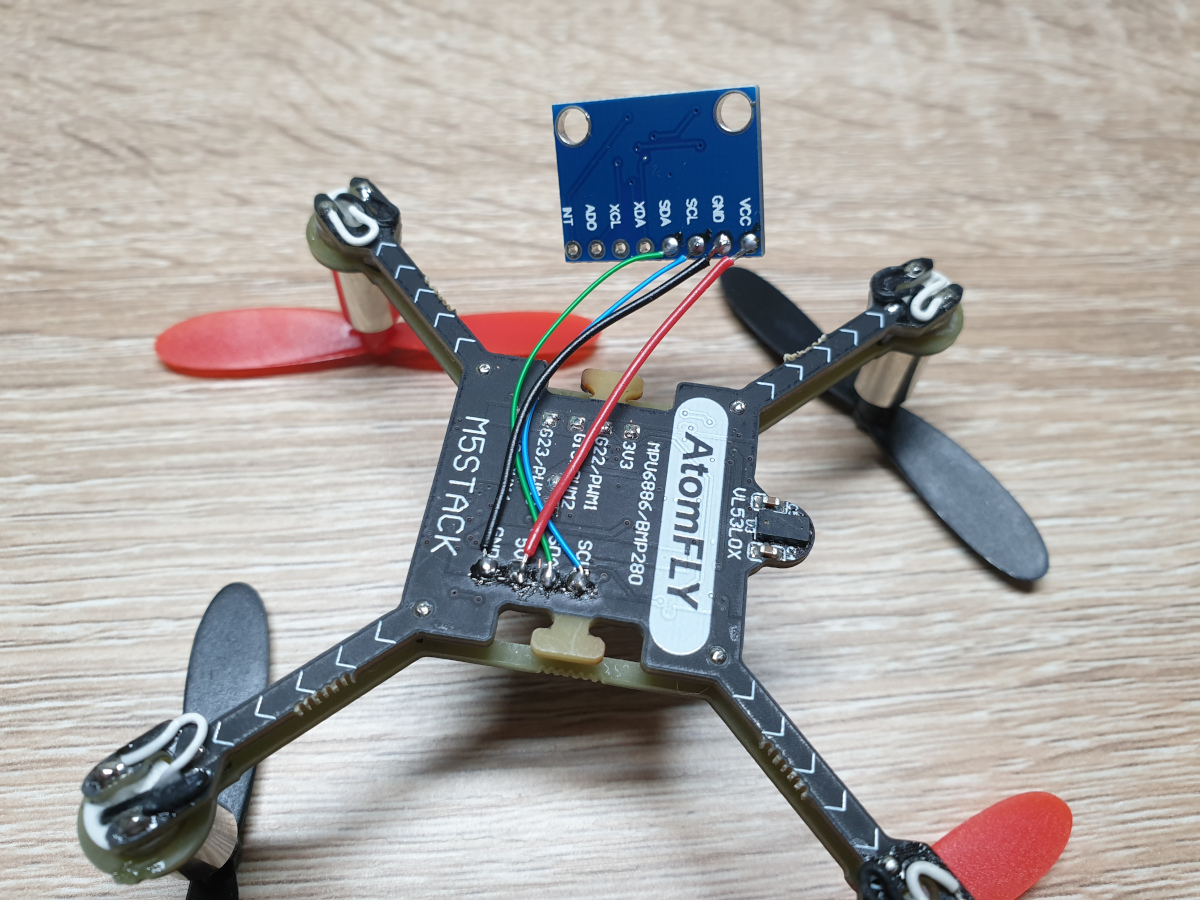
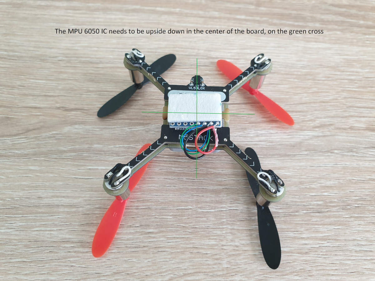
I decided to cross check the noise by adding an external 6 axis IMU. Yes you read that right, I added a MPU6050 on the back of the atomfly base, using same I2C pins (25 and 21).


Then I read both of the external and internal IMUs and compared them. The intial reading shows the external IMU is actually picking up more noise (when motors running)! So it seems the internal IMU will be more useful.
My github: https://github.com/kaisarh/atomfly
Anybody wants to share any progress/update?
-
I am waiting for a 100uF capacitor to be delivered. It is difficult to get parts easily in this COVID19 situation. Although I have a 22uF capacitor but I do not know if it would be helpful in preventing voltage drop. My progress is blocking for now.
-
@roboticbits Do you calibrate the IMU?
-
@yokonav I have tried calibration but didn't use in the last tests. In terms of reducing noise, it didn't make a big difference in my tests. Also, the yaw calculation/readings didn't quite work yet, needs fixing.
-
Are you use any movement filters?
I am having trouble trying to work out how to take 10 readings from the IMU and work out an average value to pass to the next block of code In UIFlow