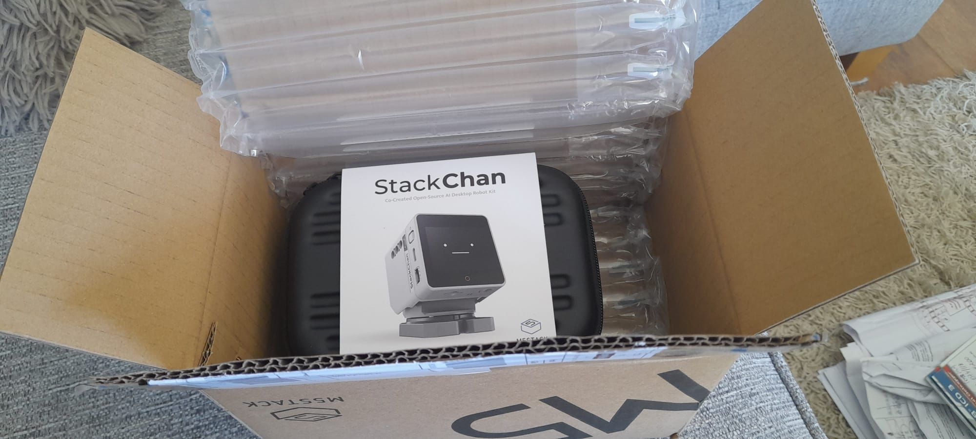
Apparently my Stackchain (sc) is "deaf". When i start the AI agent it displays the cute face and there is some motion from time to time. But no answer at all. I have chosen several languages without changes.
I have restarted the device to factory settings and have connected it again from the app. The app does recognize the sc.
Other feature non working is the Dancing app. I can start the music without any change on sc.
The firmware has been updated to the latest.
I am out of ideas. !
@scroggyg I had the same question, so I looked into it and found out it's a Molex PicoBlade 6-pin. It’s sometimes called "Micro JST", but it's really a 1.25mm pitch Molex connector.
Hello @jhfoo2
well, in my experience and with my M5PaperS3 it takes a couple of readouts (e.g. M5.update()) until the return value from the touch controller goes back to 0.
Please let me know if you find a more elegant solution.
Thanks
Felix
Hi. Thanks for posting the code. Can you confirm if this is a once-and-done write to the BMI? I code in micropython and wonder if I can run your code and then flash back to micropython and it'd still work.
@10sor
Hi, here is some documetation:
https://pikadoc-en.readthedocs.io/en/latest/index.html
and a gh-repo here:
https://github.com/pikasTech/pikaPython?tab=readme-ov-file
Hope, it helps.
zedr0k
Hi, @aliense44. I have a Card Computer ADV, a GPS/LoRa module, and an ENV III Sensor. I was trying to test the ENV Monitor ADV app, but it didn't display any information. Could you tell me how to connect it for it to work with the app? Thank you.
Like @felmue I also did a bit more testing of the low voltage flags, then enabled the charge circuit (and setting the charge voltage via bfvsel to unlimited). The clock has held time ever since.
I'm curious about how long the capacitor can run the clock when fully charged and I have disabled charging again. But my device spends most of it's time on USB power so the duration is hard to measure; so lets try to estimate it :-)
If the frequency out and I2C is disabled (inien = True) the device should typically draw 0.3 µA when on backup battery (table 5 in the datasheet).
The capacitor is possibly a ML414H; 0.07 F.
Table 3 in the datasheet says that the clock oscillator minimum voltage is 1.1v, and the start voltage is VStandby; 3.3v. So we just need to work out the discharge time.
Start with working out the equivalent resistance at 3.3v; R=Voltage/Current = 3.3/0.0000003 = 11000000 = 11 MΩ
Now use an online discharge calculator to do the 'heavy lifting'...
https://3roam.com/capacitor-discharge-time-calculator/
(I like that site; it shows the maths used)
This gives an estimated! time of 845932 seconds; which is ~235 hours, almost ten days. Which seems reasonable for a capacitor backup.
@felmue Thank you for doing the test :-)
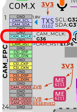
I guess this simplifies things for anybody writing a driver; but does prevent people having fun-and-games with under/over clocking the camera module.
I think it also means you cannot 'stop' the camera, which may be problem for extreme power saving. But I suspect the reset pin can be used to halt the module too.