[M5Paper] Ideas/recommendations for a revision or V2 model
-
After spending about a month tinkering with the M5Paper, a handful of shortcomings in the design have become apparent. This wishlist is what I would like to see in a future iteration of this otherwise great little device.
The first point I'd like to address is the core being used. While the ESP32 module used is fine for most purposes, Espressif has announced the ESP32-S3, which, among the upgraded cores, brings a few new features, most prominent being the built in USB stack. This would allow dropping the serial adapter chip, and using the MCU directly for USB functionality, including flashing, and even allowing the device to act as a USB peripheral (or host, for e.g. a keyboard, though power supply could be an issue).
The second point is power management. I don't want to 💩 on your work, but the M5Paper clearly received a less favourable treatment than the other M5 cores. Power supply is unnecessarily overcomplicated, and the design results in very little control over the power systems, and down the line, massive power drains unless the developer implements drastic limitations. Even the deep sleep mode of the ESP32 is drawing too much power, due to the choice of eink and touch driver (well, with the touch driver, the main issue is not having a separate power switch). Due to this, I'd like to see the return of the AXP192, which was proven quite capable in the M5Stack Core and M5Stick series. It's managed over I2C, provides better power management of components, better battery support (not to mention proper reporting of charging/discharging state and battery voltage/life reporting), and overall a better option for the overall power management. I believe it also provides drip charging, which would be crucial to extend the battery life when it's mainly mounted to a continuous power supply.
Third point is the eink driver. While the IT8951 is very capable, it was not designed with battery operated systems in mind. I've read multiple reports, not just on the M5Paper, but on various Waveshare units that also use the IT8951, that its low power/hibernate modes are unusable - the chip actually draws more power hibernated than it does in standby, and it's not a negligible amount (around 120-130mA). While this is fine for a mains powered project like a Raspberry Pi, it won't work well in the M5Paper. If I understand it right, the IT8951 basically obfuscates the waveshape messaging part of the eink protocol, providing a more manageable solution, at the price of considerably higher power usage.
The touch driver, that I'm actually happy with. The only negative I can say is that it has no separate power management, and such it cannot be disabled when not needed. With the AXP192, that should be doable, though.
Fourth point is the temperature/humidity sensor. Its unfortunate placement makes it practically useless - the proximity to the battery and the rest of the board makes temperature readings unreliable when the ambient temperature is lower than the internal temperature, unless the device was freshly powered on. The humidity sensor works, but due to the restricted airflow, which opens from the back, makes its use quite limited. Instead, I'd recommend replacing it with a combined 9DoF sensor (accelerometer, gyroscope, and magnetometer), which could provide better everyday usage, for example, for screen rotation. Though the built-in magnet might interfere.
And if we're talking about power, I think a similar POGO pin connector as the one on the M5Stack FIRE's charger base would be beneficial. A four pin connector, with I2C exposed, and the power lines connected to the PMIC, would allow for custom docking bases (e.g. a wall mount with an I2C temperature/humidity sensor, for a tear-away smart home control panel and thermostat, or a desk mount for a ticker style display for e.g. temperature). The M5Paper is clearly meant to be a semi-permanent mounted solution - most of the time it would sit in a dock, but the battery would allow for temporary mobility, such as the previously mentioned tear-away console, which mostly sits in a wall mount, but allows the user to pull it off and use it e.g. as a smart home remote.
Also another power point - a separate coin battery for the RTC. I understand that the current solution uses barely any power, however I'd feel safer if the RTC had a separate power supply in the form of a replaceable coin battery. If designed well, this would provide years of supply for the RTC (a standard CR2032 easily runs a ZigBee motion sensor for 6 to 12 months), and separate the power concerns.
Last, but not the least, the side buttons. The current solution is, honestly, quite bad. I'd rather have either three separate buttons, or a button and a full rotary encoder, or practically any other solution that provides 3-4 inputs (one of them being an interrupt/wake signal for the PMIC and the ESP32).
Otherwise, the form factor and size are perfect. LilyGO came out with a similar board around the time the M5Paper was released, same eink display but different driver, similar touchscreen, and support for both 2-pin Li-Ion, and 18650 batteries (as two "separate" model - the only difference is the connector soldered onto the board). I'll be grabbing one soon, at least to compare it to the M5Paper. The fact that the touchscreen is only available separately, and it isn't packaged as nicely as the M5Paper makes it a harder sell, but I can see the advantage of the different design.
So, to list the overall changes recommended:
- ESP32-S3 instead of the current MCU
- Replace SLM6635 (ideally with AXP912)
- Replace IT8951 with a better option (maybe just a simple shift register, similar to how the LilyGO T5 4.7 solves it)
- Connect external components (eink, touch, each external port separately) to the PMIC for separate control of power
- Replace SHT30 with IMU
- Add a POGO pin connector for power/I2C, similar to M5Go
- Replace side button with a different implementation (either three separate buttons or a rotary dial and a button)
- Replaceable coin battery for BM8563
-
good points !
- replace the (useless) temp/humidity sensor with a speaker/piezo to create a form of tactile feedback for the touchscreen ('click') or a general 'bleep' .
- a led indicator when device is on (switchable)
-
Hello,
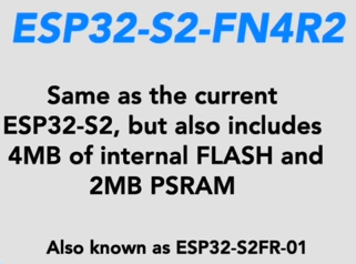
Instead of ESP32-S3, an ESP32-S2-FN4R2 allows flash and PSRAM to be integrated
 https://www.youtube.com/watch?v=iW3xD7Eo5Gw
Flash equal to M5stack, SDRAM larger than M5stack.
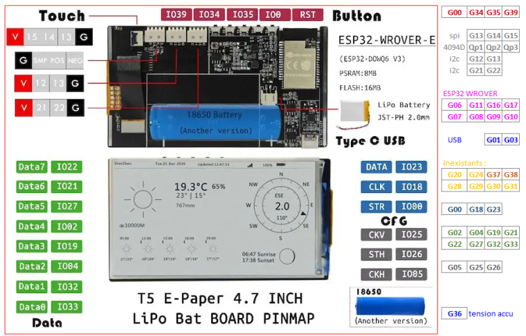
This allows to release pins to control the eInk with the 74HC4094D, 8-stage shift-and-store bus register, used as IO extander in the LilyGO T5 4.7
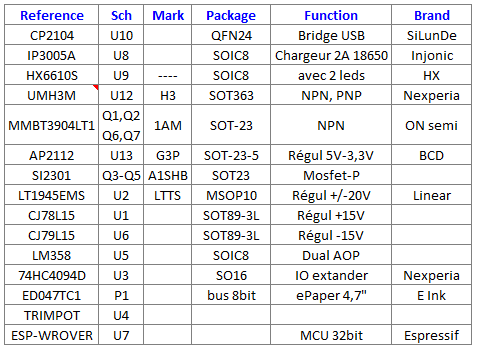
Bill of materials :
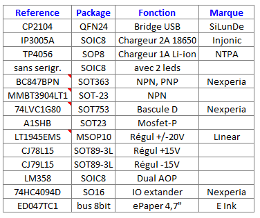
Sorry, comments are in french, my native language ....
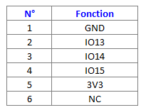
Touch connector :
Schematic : https://github.com/Xinyuan-LilyGO/LilyGo-EPD47/blob/master/schematic/LilyGo-EPD47.pdf
SYL
-
@bricox while I like the idea of using a smaller package, I think the ESP32-S3 is a better choice - it's basically the same as the ESP32-S2, however, with added bits that would be quite important for some of the possible applications of the M5Paper, including: SDIO (the S2 has no SDIO interface according to the docs), secure boot and flash encryption, and of course the S3 is dual-core instead of single-core, has larger internal memory (S2 has 320kB SRAM, S3 comes with 512kB), Bluetooth (the S2 is WiFi only)... Overall the S3 is a better package for a solution that needs to provide a bit higher performance and wider range of applications.
Also, the package you're quoting has considerably smaller flash and PSRAM. The M5Paper comes with 16MB of SPI flash, and 8MB PSRAM - 4x as much as the quoted package. I think it's a good trade-off for slightly less space on the board, and a handful less pins. The LilyGO T5 4.7 made the display work with a shift register, while still having the necessary pins available for external ports.
The reason why I'd like to see an update to the M5Paper is simply because of this revision's design faults. An ESP32-S2 would be a massive downgrade, and it's not something I'd like to see in a revised, upgraded version that fixes a number of issues, only to bring in a handful of limitations and setbacks.
-
@bricox
bill of materials most complete
SYL -
I think that M5Stack is not going to switch to ESP32 S2 or S3 any time soon. At least not before Micropython has a port for these chips.
-
@fonix232
on https://www.espressif.com/en/support/documents/technical-documents
No pdf for S3, just C374HC4094D, IO extander, needs many pins
ESP32-D0WD => 48 pin (m5paper)
ESP32-C3-FH4 => 32 pin, with 4 Mo flash only
ESP32-WROVER => 38 pin (LilyGo), with 16 Mo Flash and 8 Mo SDRAM
ESP32-S2-FN4R2 => 56 pin, with 4 Mo flash and 2 Mo SDRAM integratedSYL
-
@bricox
Touch connector most complete

-
@bricox said in [M5Paper] Ideas/recommendations for a revision or V2 model:
@fonix232
on https://www.espressif.com/en/support/documents/technical-documents
No pdf for S3, just C374HC4094D, IO extander, needs many pins
ESP32-D0WD => 48 pin (m5paper)
ESP32-C3-FH4 => 32 pin, with 4 Mo flash only
ESP32-WROVER => 38 pin (LilyGo), with 16 Mo Flash and 8 Mo SDRAM
ESP32-S2-FN4R2 => 56 pin, with 4 Mo flash and 2 Mo SDRAM integratedSYL
No data for the S3 exist because it officially doesn't exist.
Some WIP samples are out in the wild but the information the testers have and IDF support is incomplete as the silicone can change. -
@ajb2k3
Thank you for this information ... ;>)...
Unexpected Maker have some for board development
https://www.youtube.com/watch?v=iW3xD7Eo5Gw
SYL -
@fonix232
2 months ago, you said :
"Uhm... Pardon my ignorance but according to my research the IT8591 is a full-blown EPD timing controller, not just a bus register. I don't see how the 74HC4094D would be an alternative (most definitely not a drop-in replacement)."
Now :
"Replace IT8951 with a better option (maybe just a simple shift register, similar to how the LilyGO T5 4.7 solves it)"
Congratulations for this nice evolution in the absence of my late answer ... ;>) ... -
Hello,
We can also replace the MCU IT8591 with a low power MCU as STM32L0 or STM32L4 family and keep le SPI bus. -
Hi guys
currently the INT line from the touch IC is connected to GPIO36 of the ESP32. This is a poor choice for two reasons:
- GPIO36 is an input only GPIO, but to put the touch IC into sleep mode the ESP32 needs to be able to drive and control the touch INT line.
- GPIO36 (and GPIO39 for that matter) produce 'ghost' inputs if used as interrupts and WiFi is in use with a power save mode enabled. (This is a hardware limitation / bug of the ESP32.)
Thank you for listening.
Felix
-
@bricox yep, did some research and realised how the shift register can be used in place of the controller. Not sure if it's a definitely better solution. However I like your idea of using a smaller, more power-efficient MCU, especially if it has some deep sleep mode with quick wake.
I was also wondering - the IT8951 schematic shows that internally, it's a RISC-V microcontroller with a bunch of attachments (USB, I2C, SPI and SDMMC host interfaces). It also supports (apparently) firmware upgrades. I could not find any sources unfortunately, but, in theory, if we had those sources... Would it be possible to write a more optimised version of this firmware, one that would reduce the power usage? Obviously we don't even know what kind of RISC-V core it has, if it has any low power modes (though the fact that a "sleep" mode is supposedly implemented in it would suggest that it is capable of some sort of sleep mode, the data sheet even details what is powered and how in which state), and so on. Sadly the only documentation we have on this chip comes from an early draft (v0.2.x.x, from Waveshare), and even M5Stack decided not to attach this datasheet to the documentation. I can't help but wonder if they even got the firmware source and build environment, even if under an NDA.
-
Also, my TTGO T5 4.7 arrived, finally. Overall, a nice piece, although a bit rough around the edges compared to the M5Paper. Overall, the PCB seems to be better designed, everything is nicely sectioned apart. But, LilyGO did bum it up, the EPD connector is just sliiiiightly further from the edge than the ribbon itself, which results in some twisting of the cables, and I'm not sure I'm comfortable with it...
One thing I'm extremely unhappy with is the battery connector. I opted for the 18650 model (the difference is literally just the connector soldered - with a J2 female connector and 5 minutes of soldering I could convert it easily, but I want to use it with 18650 batteries for easy battery swapping), and the metal wings are outrageously bad quality. They are too rigid, and the edges were not finished properly, and I managed to cut open the wrap of one of my cells on the first insert. This was with great attention paid to the insertion process, and ~3 hours spent on filing down the connector edges (don't worry, I covered the rest of the board with painter's tape, and blasted it with some compressed air to make sure no metal fragments linger around). I think once I have a finalised 3D printed case for it, I'll remove the connector and replace it with a homemade spring-loaded version.
Another, interesting thing I noticed while digging around in the guts of the M5Stack... Apparently, there's a second, unpopulated USB-C port on the board.
None of the schematics mention it, and I can't really trace it, since the components are too tightly packed:
It's right next (or, in the orientation of the above picture, below) the SD card slot. I'm not sure if it's meant to be a power port only (though the fact the data lines are labeled makes me think it isn't), or if it's directly connected to the IT8951 (which would make sense, since that MCU has a built in USB interface, which allows controlling and even updating the controller).
On another note, I reached out to ITE and requested the release of the source code + dev environment for the IT8951 firmware. With any luck, we should have the sources soon, and maybe we can put together a better, less resource-hungry one, just to make the M5Paper that tiny bit better.
EDIT:
I've been going through the M5Paper schematic to check that USB port and also the USB hookup of the IT8951... First thing I noticed is that the schematic says the M5Paper is supposed to have the IT8951E-64, yet we only have the regular IT8951E.
However, I've found the unpopulated Type-C port on the schematics - no idea how I missed it the first time around. It's J8, labeled
USB-TYPEC/NC, and its data pins are connected to the IT8951's USB OTG pins, plus the VUSB rail. Meaning that with a quick solder job, one could add a secondary USB-C port that would allow direct communication with the IT8951. With a custom firmware, we could coax that MCU to act as, well, any kind of USB peripheral. And who knows, maybe other stuff could be also offloaded to it. IF we can get the source code for the damn controller. And that's a very big if. -
@fonix232
In my professional activity, I use the STM32L476.
Its average power consumption is 15-20mA at 80 MHz.
I use "Stop 2" mode to reduce consumption => 2.3µA (5µs wake-up with many sources).
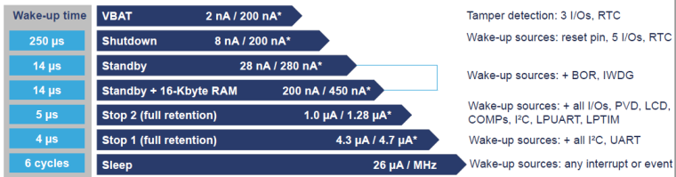
In addition, it has its own RTC with calendar and the ADCs are most linear than ESP32. -
@fonix232
USB-TYPEC/NC is not a real USB port because no bridge.
The connector is USB-C but the line is UART only. -
@bricox are you sure about that USB-C port? Because according to the schematics, it goes to the USB lines of IT8951 (IT_DBG_P and IT_DBG_N, pins 52 and 51 on the IT8951, which matches the official IT8951 documentation - the Waveshare adapter board also connects those pins to its USB interface), while the UART lines of it connect to a grayed out (presumably not in the final design?) 4-pin port called J10. As the IT8951 has a built in USB interface, and the default firmware (at least on Waveshare panels) even provides a UMS interface with custom, I believe SCSI, commands similar to the SPI protocol.
There's a red symbol on both the M5Paper and the Waveshare IT8951 driver board's schematics where the IT8951 pins 51 and 52 connect to the USB port, which I do not know the meaning of. Could you enlighten me?
@m5stack could we please get some information on the IT8951? Of course within your NDA limitations. Things like changes you've managed to its firmware (apart from the display specific things like resolution, waveform generation, etc.). Is it possible to modify this firmware to reduce power consumption, introduce the SLEEP mode that is apparently missing, and to update it without hardware modifications (i.e. is there a firmware update solution via SPI, or only USB)?
-
@fonix232
My apologies, I don’t know how I made that big mistake ... ;>)
You’re right, it’s definitely a native USB.The red symbol is, for me, that printfoot USB-C connector is on the pcb but not welded.
This part of the schema is not completely greyed out as J10 because the 2 resistors R1 and R60 are welded.
 The Google search with this image did not succeed.
You’d have to look in the symbol library of the design software, I think it’s Altium... -
@bricox The same red symbol appears on the Waveshare schematics for the IT8951 Pi HAT, in the same place (although the M5Paper schematics have the symbol on both the IT8951 and the USB port side, whereas the Waveshare one only has it on the USB port). And based on the second page of that PDF that shows the exact traces, there's nothing between the IT8951's pins and the USB port, just the trace. No resistors, capacitors, nada.
Nonetheless, in my opinion, that USB port could be "easily" soldered in (by someone who knows how to solder properly, i.e. not me), and used to directly communicate with the IT8951, and power the device in the process (the voltage line of this port is also hooked up to the PMIC, just like the main USB port).