How to use SPI with the stack ??
-
Hi guys,
today I spent some time getting my MCP3204 working. It´s a 4 channel ADC with an SPI Bus.
I connected the MCP like this:#define SPI1_CLK 18 // D -> Clk -> Pin 11 #define SPI1_MISO 19 // Q -> D Out -> Pin 10 #define SPI1_MOSI 23 // -> D In -> Pin 9 #define SPI1_SS 16 // -> CS -> Pin 8It´s working as expected as far as I don´t use any display stuff from the M5 Stack.
As soon as I ad the following to my code:
 M5.begin(); // true, false, false);
 M5.Lcd.printf("TEST");
things getting wired. The readings of my MCP3204 are wrong.
I convert the AD values to temperature vales since I use some BBQ sensors. And the results are about 2 degrees wrong when adding the M5 Display.
Example: Reading temp without Display -> ~21° and with display ~23° or sometime ~17°
I can do some addition checks with the plain AD values to get a better understanding.But anyway ... What´s wrong in using the SPI bus for a second device?
Are there any drawbacks i don´t know? Any issues?Maybe someone has some explanation for this topic.
Dominik
-
Hi Guys,
I think I figured out the main problem.It has nothing todo with the SPI bus ... It´s the 3,3V line.

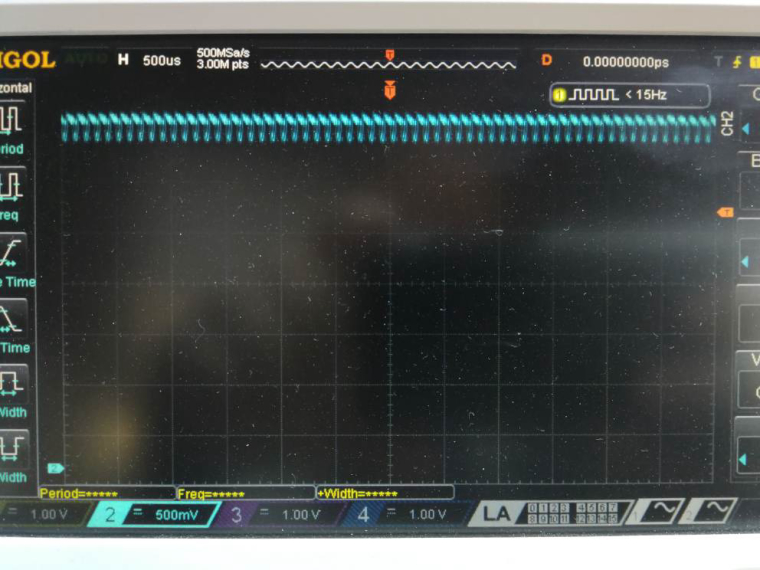
Take a look at the picture. If you set the LCD to 80 (~33%) brightness then the PWM signal is extremly present on the 3,3v line ... And the MCP3204 don´t like that :-)
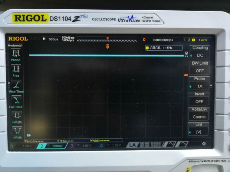
And this is a picture with 255 (100% on) brightness ...

No further explanation needed ...
Dominik
-
Thanks, it's useful.
-
@moelski Have you tried adding a small capacitor to ground?
-
Hi Rob.
Yes there are 100nF directly at the Power supply of the Mcp3204.
But that won't help. I Ordered some lm4040 to have a clean voltage reference.
I think that will help.Regards
Dominik