🤖Have you ever tried Chat.M5Stack.com before asking??😎
    M5Stack Community
    • Categories
    • Recent
    • Tags
    • Popular
    • Users
    • Groups
    • Search
    • Register
    • Login

    M5StickC : how to switch 5V out off?

    M5 Stick/StickC
    3
    13
    2.6k
    Loading More Posts
    • Oldest to Newest
    • Newest to Oldest
    • Most Votes
    Reply
    • Reply as topic
    Log in to reply
    This topic has been deleted. Only users with topic management privileges can see it.
    • felmueF
      felmue @Kabron
      last edited by

      Hello @HappyUser

      you can use this function to control the output of 5 V out (and Groove port):

      M5.Axp.SetPeripherialsPower(true or false);
      

      Thanks
      Felix

      GPIO translation table M5Stack / M5Core2
      Information about various M5Stack products.
      Code examples

      KabronK 2 Replies Last reply Reply Quote 2
      • KabronK
        Kabron @felmue
        last edited by Kabron

        This post is deleted!
        1 Reply Last reply Reply Quote 0
        • KabronK
          Kabron
          last edited by

          I tested it - does not work at all

          1 Reply Last reply Reply Quote 0
          • KabronK
            Kabron @felmue
            last edited by Kabron

            @felmue It only switched 5V to Vbatt
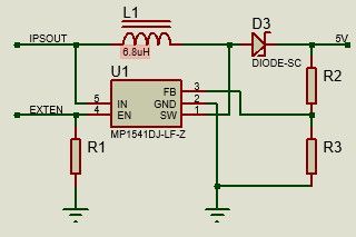
            I see the only way to reconnect EXT_BOOST_EN of the BOOST converter to VESP_3V3.

            felmueF 1 Reply Last reply Reply Quote 0
            • felmueF
              felmue @Kabron
              last edited by felmue

              Hello @Kabron

              hmm, I've tested with an M5StickC (not Plus, not Plus2) powered by USB-C (or battery) and an LED attached to the Groove port.

              I agree, EXT_BOOST_EN needs to be turned on, which is exactly what the function I pointed out does. It sets bit 2 of register 0x10 of the AXP. See here. And here - page 34.

              Edit: I just remembered, I think there was a similar discussion a couple of years ago. EXTEN actually seems to exist in two places. Bit 2 in register 0x10 and bit 6 in register 0x12.

              Maybe try to manipulate bit 6 in register 0x12 to see if that works for you?

              Thanks
              Felix

              GPIO translation table M5Stack / M5Core2
              Information about various M5Stack products.
              Code examples

              KabronK 1 Reply Last reply Reply Quote 0
              • KabronK
                Kabron @felmue
                last edited by Kabron

                @felmue I tested it:
                void AXP192::SetPeripherialsPower(uint8_t state) {
                if (!state){
                Write1Byte(0x10, Read8bit(0x10) & 0XFB);
                Write1Byte(0x12, Read8bit(0x12) & 0XBF);
                }
                else if (state) {
                Write1Byte(0x10, Read8bit(0x10) | 0X04);
                Write1Byte(0x12, Read8bit(0x12) | 0X40);
                }

                EXT_BOOST_EN controlled correctly, DC-Boost stops generating, but bypassed input Vbatt to 5V output.

                What an idiot designed this part of schematic?

                I could not identify DC-Boost IC(Sot-23-5 marked IB3KB)/

                1 Reply Last reply Reply Quote 0
                • KabronK
                  Kabron
                  last edited by

                  So, according to schematic switching off 5V is fundamentally impossible. IPSOUT via L1 and D3 allways present at output.
                  DCBoost.jpg

                  felmueF 1 Reply Last reply Reply Quote 0
                  • felmueF
                    felmue @Kabron
                    last edited by

                    Hello @Kabron

                    I start to think that maybe the DC/DC IC has been changed over time in the M5StickC. The DC/DC IC in mine is marked SCAJF and the externally connected components look suspiciously like the 5VOUT_BOOST in the M5StickCPlus schematic.

                    This would at least explain the different results regarding on/off capability.

                    Thanks
                    Felix

                    GPIO translation table M5Stack / M5Core2
                    Information about various M5Stack products.
                    Code examples

                    1 Reply Last reply Reply Quote 0
                    • KabronK
                      Kabron
                      last edited by

                      Definitelly, M5SticC and M5SticC Plus have different schematics. DC-Boost in M5SticC Plus is sgm6603-5.

                      felmueF 1 Reply Last reply Reply Quote 0
                      • felmueF
                        felmue @Kabron
                        last edited by

                        Hello @Kabron

                        I beg to differ. At least between my M5StickCPlus and M5StickC the DC/DC boost circuit and IC look suspiciously identical.

                        M5StickCPlusVsM5StickC_240617.png

                        on the left: M5StickCPlus; on the right: M5StickC

                        Thanks
                        Felix

                        GPIO translation table M5Stack / M5Core2
                        Information about various M5Stack products.
                        Code examples

                        KabronK 1 Reply Last reply Reply Quote 0
                        • KabronK
                          Kabron @felmue
                          last edited by Kabron

                          @felmue I draw schematic above from my exemplar. Obviously it's too old.
                          IC is SOT-23-5 and its marking corresond with MP1541 datasheet.

                          The root of the evil is M5STACK's absolutely lackadaisical documentation for all the products.

                          1 Reply Last reply Reply Quote 0
                          • First post
                            Last post