Simple fix when upload fails.
-
After much fiddling around I managed to connect to it. However it is unreliable. This thing is a big disapointment. It is obvious a lot of work went into this thing, but they should have put in a little more to get it to work right out of the box.
You can get Various Arduinos, ESP8266's and ESP32's for much less and they just work.
-
so sorry, pls try this. -
try what? add a cap? what type and volts? where can I get 1 cap? how about I send this back and you fix it so it works?
-
++
-
Here is how I see it, I already spent over $40.00 for this thing. Yes, I can spend another $3.50 and order some caps, wait 5 to 6 weeks for them to arrive and they may or may not solve the problem. If this is a known issue you should have included a cap with the device.
I tried 3 caps, 2 electrolitica and a polyester one. the result is the same, you need to try to upload the sketch multiple times to maybe get it to work once.
-
JimiT and ElectroMagnus, thank you for your help
-
++
-
Hey @Stanszal ... I just got one of these and had issues with getting the uploading working. I found that if I reset the device and got the timing right then it would work. You just reset it while the "...____" message is writing. I can't tell you when to do it specifically, you just have to guess.
-
Mine worked great until today. I really don't understand why it stopped working today.
-
Hi guys, just got mine in today and it kept resetting while trying to program. Started at the forums and found this post.
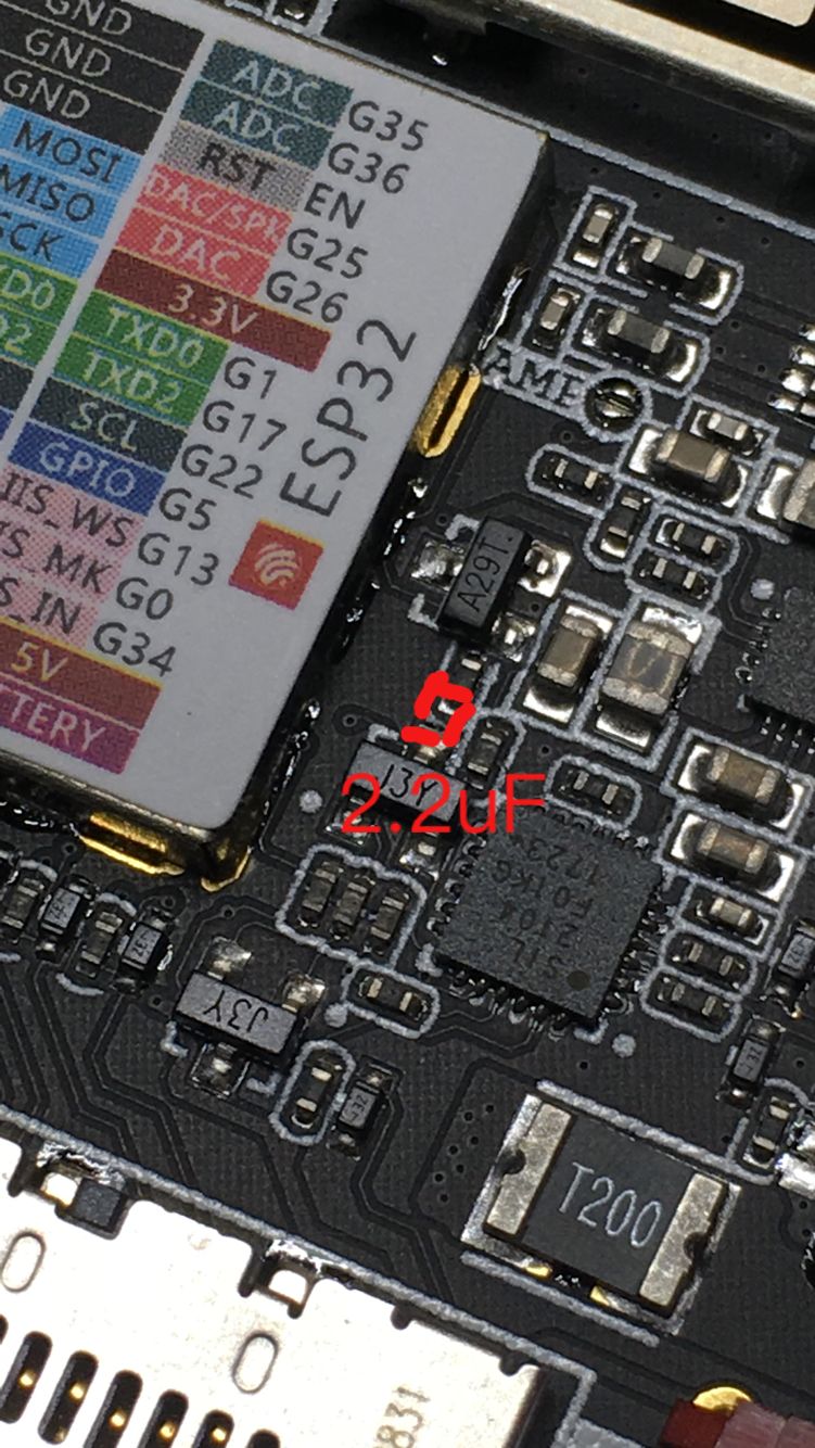
As a R&D engineer let me first just say the guys at m5Stack know what they are doing on the hardware side. It's an exceptions build, But looking at the schematic, i am kinda shocked they dont have a cap on the reset line.I tried 3 values and all worked. 0.1uf, 2.2uf & 10uf. Would not go higher than 10uf though.
I stuck a 0.1uf cap on the reset pin to gnd, and mine works just fine now, Typically in this circuit anything =<10uf should work just fine.
In the photo I put a 0805 cap, there. It would be best to stick a 0603 there but I didn't have any.
You can get these locally at mouser or digikey.
0.1uf cap at MouserFor those of you who dont have solder skills like this you can use a through hole cap like this one externally on the box from "RST" to "G". polarity does not matter for this ceramic cap.
0.1uf Through Hole Cap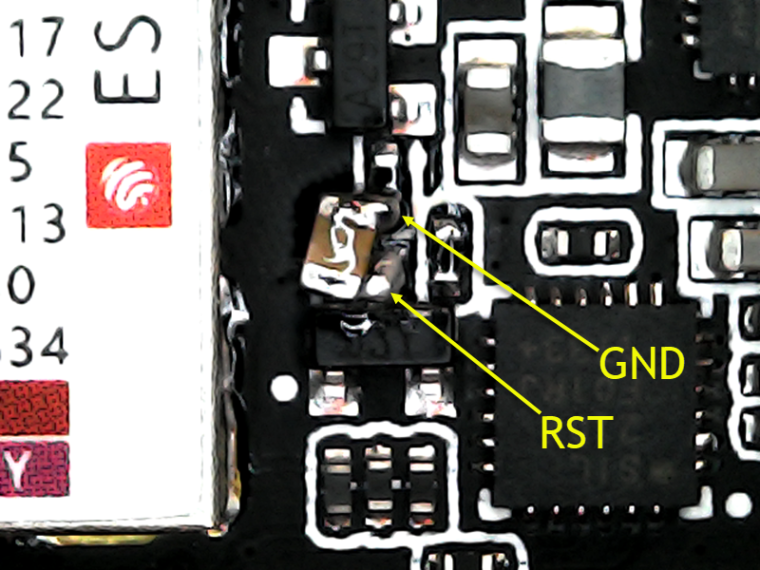
-
I just wanted to say that a 10 uf cap worked great for me!
-
A 100nF SMD capacitor soldered between EN (the collector of VT2) and the shield of the ESP32 module did the job for me.

-
As a heads up - I was having the same bang your head against the wall problem as Stanszal trying to get the "temporary" capacitor fix to work. Turns out that in addition to the capacitor being needed, there may be issues with the header connections on some of the boards. None of the GND\RESET connections worked with the capacitor thru the bottom plate. Pulled the bottom plate and plugged the cap right into the MBus header GND\RST on the system board and it's worked every time - plan is to solder the CAP patch once I get a small one.
So - besides the capacitor issue (I really hope the fabricator reads this stuff and comes up with a fix), you all need to be aware as to why soldered boards are much preferred over solderless breadboards and header stacks. Less likely to have poor connections via solder. I love the compactness and modularity of the M5Stack (part of why I picked one up to play with) but this just underscores that you need to be wary of the header pin connections on the modules. The short pins and sockets and tight tolerances to make this what it is looks prone to connection problems.
-
Messed around with the M5Stack again a bit this morning. One thing that seemed to help the pin connections between the bottom plate and MBus socket was to work across the plastic pin guides and press it down closer to the base plate board. I'd done a few more sketches to upload with the capacitor plugged into the MBus socket. When I put things back together, I couldn't get it to power on with the base plate so I tried pressing the header pin plastic spacer down to make sure I had better contact into the MBus socket. This fixed the battery power problem AND has (at least short term) allowed me to use the external temporary capacitor via the baseplate sockets and pins. Suspect it explains Stanszal's similar problem and why some other have reported the external capacitor approach not working after a while. I am going to have to keep in mind that the M5Bus header and mating pins have a very finite insertion life and to try and be sure I seat things well if I use proto-, battery-, etc., expansion boards.
-
@kentinker Installing two M3 screws of the proper length in the baseplate my help tightening it down.
It is a pity a set of these M3 screws is not included by default.
Serge — http://hamwaves.com/iot/
-
++
-
@jimit Over here in Europe, metric M3 screws are pretty easy to come by. However, I can imagine this to be more difficult in the US.
Since, I have the optional 850mA battery module installed, it requires slightly longer screws. From what I recall, 20mm length was just not long enough. Hence, I think 25mm length is what I need. I still need to make the trip to the hardware store, though.
Serge — http://hamwaves.com/iot/
-
++
-
@on4aa Yes, that crossed my mind as well. My main point in posting was because it seemed that the bottom plate pins being seated in the MBus socket was causing some of the issues others noted. The quick fix pressing the plastic pin separator down (all the way across the 2x15 set) toward the bottom PCB gave better pin to socket engagement and cleared the problem. As it was received, the available pin length to seat into the MBus header was just a tad short.
-
++