Connect COM.LTE to CoreS3?
-
Hi all!
I just got my first CoreS3 yesterday. I've been using the original Core with COM.LTE modules for a product/project I've been working on. I'd really like to start using the CoreS3 instead, as it has so many more features that are perfect for my project. But it looks like the M-BUS connector has a slightly different pinout. Am I able to use the COM.LTE with the CoreS3?
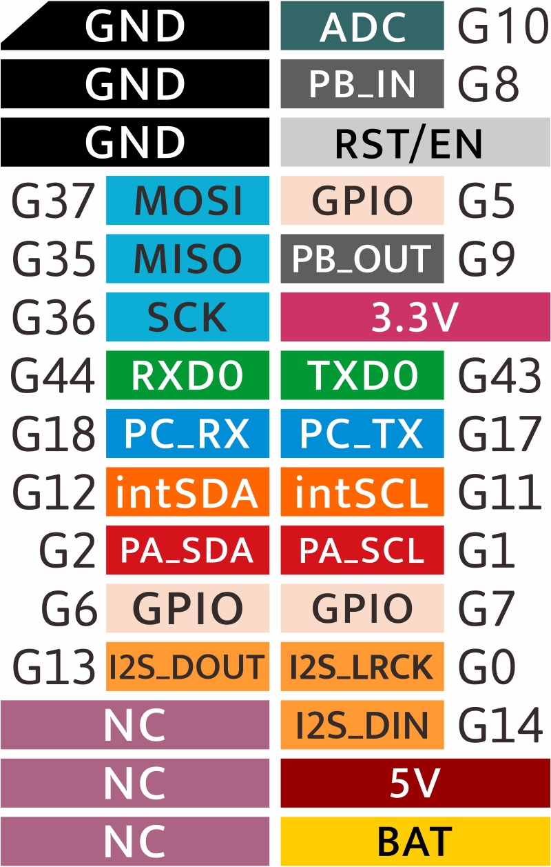
By default, the COM.LTE uses pins 5 and 13, which are listed as the GPIO and IIS_WS pins, respectively. On the CoreS3, those same pins are PA_SCL G1 and GPIO G7. Is the PA_SCL pin the SCL on the external red I2C connector? I do need that for some sensors.
I could use the DIP switches to change from using pin 5 to using 15 or 16. 15 was formerly IIS_OUT but is now I2S_DOUT, which I'm assuming is for the speaker, which I need. 16 was formerly RXD2 but is now PC_RX G18. Not sure what that pin is for.
Thanks! I'm so excited to get this new unit going!
aezero
-
Hello @aezero
You are correct, on M5CoreS3 GPIO1 and GPIO2 are used for external I2C.
I suggest you set COM.LTE to use pins 16 / 17 and then use GPIO18 / 17 in your code. AFAIK PC_RX and PC_TX are the second serial.
Thanks
Felix -
@felmue
Hi Felix! Good to hear from you again!Thanks for the clarification! The second serial connection is the blue connector, right?
-
Looking at the pinout diagrams with some refreshed eyes and I see it now... "PA" is short for "Port A" and "PC" is short for "Port C". And PA has a red background, like the red Port A connector, and PC is in the same light blue as Port C's connector.
-
Hello @aezero
thank you for pointing that out as I haven't noticed that myself - even the background color matches the connectors.
Thanks
Felix -
And on further examination, there's the dark grey PB_IN and PB_OUT pins, at G8 and G9. The splash screen when you power it on shows G8 and G9 are on Port B (there's a typo, saying "Port.C" but it's in the position of the black Port B connector).

-
I just made another discovery. If you power it up with the factory demo software, go the home screen, and then tap on "CORES3" six times, it puts you into a factory test mode
-
I have the M5CoreS3 and the Com.x LTE, not having any success communicating with the COM.X LTE. the dips are on the default 5/13.
what should they be set too? and is there any simple Example Test of LTE for me to test and follow??I see this comment
"I suggest you set COM.LTE to use pins 16 / 17 and then use GPIO18 / 17 in your code. AFAIK PC_RX and PC_TX are the second serial."not sure if just Dip 5 should change to 16 or 17?? help appreciated.
also in the Code is there a command to tell how to communicate with those different PINS??
first time use of the LTE.
thanks -
Hello @Cohen
please find a simple test for the communication between M5CoreS3 and COM.LTE module.
In the COM.LTE module set the DIP switches as follows:
15 - off
 5 - off
16 - on
13 - off
 0 - off
17 - on
Note: my COM.LTE module takes about 15 seconds (after power on) until it is ready and responds with
AT OK.Thanks
Felix -
-
Thanks that did it.
I got a res: AT OK.thanks.
I am trying to use TinyGSM
has any one got it working with he Core3 COM.X LTE?but with no luck. get the following:-
22:44:52.276 -> [6988] Trying baud rate 115200 ...
22:45:02.304 -> [16999] Trying baud rate 57600 ...
22:45:12.314 -> [27009] Trying baud rate 38400 ...
22:45:22.312 -> [37019] Trying baud rate 19200 ...
22:45:32.324 -> [47029] Trying baud rate 9600 ...
22:45:42.325 -> [57039] Trying baud rate 74400 ...
22:45:52.334 -> [67049] Trying baud rate 74880 ...
22:46:02.336 -> [77059] Trying baud rate 14400 ...
22:46:12.356 -> [87069] Trying baud rate 28800 ...
22:46:22.358 -> [97079] Initializing modem...
22:46:32.393 -> [107111] Failed to restart modem, delaying 10s and retrying
22:46:32.393 -> [107111] Initializing modem...
22:46:42.440 -> [117143] Failed to restart modem, delaying 10s and retrying
22:46:42.440 -> [117143] Initializing modem...
22:46:52.451 -> [127175] Failed to restart modem, delaying 10s and retrying
22:46:52.454 -> [127175] Initializing modem...Thanks
-
Got a bit further in the quest.
I added the following:-
void setup() {
// Set console baud rate
SerialMon.begin(115200);
delay(10);SerialAT.begin(115200, SERIAL_8N1, 18, 17, false);
delay(3000);
modem.restart();and got some responses
23:06:21.706 -> [14189] Wait...
23:06:27.695 -> [20189] Trying baud rate 115200 ...
23:06:30.064 -> [22535] Modem responded at rate 115200
23:06:30.064 -> [22535] Initializing modem...
23:06:35.068 -> [27555] ### TinyGSM Version: 0.11.7
23:06:35.068 -> [27555] ### TinyGSM Compiled Module: TinyGsmClientSIM7600
23:06:45.272 -> [37756] Failed to restart modem, delaying 10s and retrying
23:06:45.272 -> [37756] Initializing modem...
23:06:55.486 -> [47957] Failed to restart modem, delaying 10s and retrying
23:06:55.486 -> [47957] Initializing modem...
23:07:03.779 -> [56269] ### TinyGSM Version: 0.11.7
23:07:03.779 -> [56269] ### TinyGSM Compiled Module: TinyGsmClientSIM7600
23:07:03.843 -> [56316] ### Modem: SIMCOM SIM7600G-H
23:07:03.843 -> [56316] ### Modem: SIMCOM SIM7600G-H
23:07:03.877 -> [56369] ### Modem: SIMCOM SIM7600G-H
23:07:03.877 -> [56369] Modem Name: SIMCOM SIM7600G-H
23:07:03.910 -> [56397] Modem Info: Manufacturer: SIMCOM INCORPORATED Model: SIMCOM_SIM7600G-H Revision: SIM7600G_V2.0.2 IMEI: "redacted" +GCAP: +CGSM
23:07:03.910 -> [56397] Waiting for network...
23:07:03.975 -> [56440] Network connected
23:07:03.975 -> [56440] Connecting to vsh.pp.ua
23:07:04.008 -> [56482] ... failed
23:07:04.008 -> [56482] Requesting current network time
23:07:04.008 -> [56484] Couldn't get network time, retrying in 15s.
23:07:18.986 -> [71484] Requesting current network time
23:07:19.025 -> [71486] Year: 2024 Month: 1 Day: 26
23:07:19.025 -> [71486] Hour: 23 Minute: 7 Second: 3
23:07:19.025 -> [71486] Timezone: 11.00
23:07:19.025 -> [71487] Retrieving time again as a string
23:07:19.025 -> [71506] Current Network Time: 24/01/26,23:07:18+44
23:07:19.185 -> [71672] Battery charge state: 0
23:07:19.185 -> [71672] Battery charge 'percent': 0
23:07:19.185 -> [71672] Battery voltage: 3.80
23:07:19.219 -> [71691] Chip temperature: 37.00
23:07:19.219 -> [71691] End of tests.
Hello! It looks like you're interested in this conversation, but you don't have an account yet.
Getting fed up of having to scroll through the same posts each visit? When you register for an account, you'll always come back to exactly where you were before, and choose to be notified of new replies (either via email, or push notification). You'll also be able to save bookmarks and upvote posts to show your appreciation to other community members.
With your input, this post could be even better 💗
Register Login