Simple PWM example does not work
-
I found a simple PWM example for the esp32 using Arduino IDE. This does not seem to work for and Atom Lite. Do I need to use another controller? Or something else missing.
This is the example:
const int ledPin = 22;
const int freq = 5000;
const int ledChannel = 0;
const int resolution = 8;void setup() {
Serial.println();
ledcSetup(ledChannel, freq, resolution);
ledcAttachPin(ledPin, ledChannel);
}void loop() {
for (int dutyCycle = 0; dutyCycle <= 255; dutyCycle++) {
ledcWrite(ledChannel, dutyCycle);
delay(25);
}
for (int dutyCycle = 255; dutyCycle >= 0; dutyCycle--) {
ledcWrite(ledChannel, dutyCycle);
delay(25);
}
Serial.print(".");
} -
@Kees Atom Lite or Atom S3 Lite?
What are you controlling with PWM?
-
For now a LED (but finally I hope to control a 5V linear actuator. The LED example is to experiment.
-
@Kees Well, your code as supplied worked on a similar board that I have, an AtomS3. (I used pin 5) Your supplied code should work on your Atom Lite (non-S3 version).
My observation is that the tiny decal on the back showing the pins is hard to read. It is easy to offset one pin.
Does the LED light when across 3.3v to G ? -
@teastain
The LED won't light up. However I did measure about 3.3V on the output pin before. I expected this to increase and decrease. It did not.
Now I don't have time anymore, but when have another suggestion I will try it tomorrow.
Thanks! -
@Kees The Voltmeter measures the peak voltage and so pulses of 3.3 would measure as 3.3V despite the pulse width.
-
@Kees you did change the LED PIN number to match the atom did you?
-
@All I finally added a second LED that I controlled with a digitalWrite and that worked fine (even better without the resistor used in the schematic). After playing with the connections (again) finally I saw the light (literally). I believe the contact of the pin in the Atom Lite does not make good contact (have to find something that does, otherwise quite unreliable). So this seem to work. Thank you guys for that.
However I still have a question about using it for the linear actuator. It has a three wire input. A brown one, probably ground, a red one (5V? (document states Voltage 3.5 - 6V) and an orange one (control signal). I can not find much information about connecting such a device. Tried several setups with different frequencies (1000-2000), but nothing seems to work. Maybe an external adapter is needed. Any idea how to connect it?
-
@Kees The outputs are rated 20mA, so I always use a resistor, 330 - 1k Ohm.
Is it Atom Lite or Atom Lite S3, makes a difference.
The linear actuator will require a separate power supply, at minimum.
What facts do you know about the 'linear actuator'? -
@teastain On the controllers it says Atom Lite, nothing more. Is there another way to distinguish them, does is otherwise say Atom Lite S3?
I applied a separate power supply. This what the specs tell:- The mini electric push actuator is equivalent to a linear motor : through the red and black two power lines to provide DC power supply DC 6-7.4V to the motor rotation, and drive the telescopic rod to achieve expansion, and stroke in any position can stop, can be self-locking.
2.With PWM electric control : can be controlled by the receiver, can adjust the speed and direction.
3.PWM module parameters :
Weight:0.4g
Size:12x8.5mm
Voltage:3.5-6v
Continuing current:1A ,The biggest current: 1.5A
PWM range:1000~2000US
BEC output: No
Running direction: two-way, can be forward and reverse.
Applicable motor:Brush motor.
Maybe this is enough. I could not get it working. Except for one moment it completely expanded, however I not reverse it or achieve another position. Hope you have some advice for me.
- The mini electric push actuator is equivalent to a linear motor : through the red and black two power lines to provide DC power supply DC 6-7.4V to the motor rotation, and drive the telescopic rod to achieve expansion, and stroke in any position can stop, can be self-locking.
-
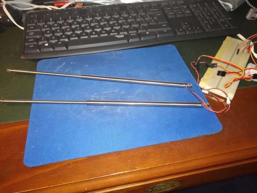
@Kees Can you take a picture of it?
It may be a RC servo motor rotating to power the screw.
In which case you would use the cryptic 'ledc' library or a newer ESP32 Servo library.
See M5Stack servo products.
You should gingerly retract the rod and then control its position with ledc set for servo applications and select, program for smaller movements.#include <esp32-hal-ledc.h> //in setup ledcAttachPin(25, 1); void SetServoPos(int pos) { ledcAttachPin(26, 1); delay(100); uint32_t duty = (((servoWritePos / 180.0) * 2000) / 20000.0 * 65536.0) + 1634; ledcWrite(1, duty); delay(100); //ledcDetachPin(26); delay(100); posOld = pos; }some samples that may not work for you, but to give you the idea
-
@teastain Thanks. A few questions. The first ledcAttachPin does not apply here I presume. The math is not clear to me. 180 probably has to do with degrees, 2.000 perhaps frequency, then a 20.000.0 I do not understand, the 65536 is probably a 2 byte shift and then another number (16340 I do not understand. Perhaps you have a link to a site with some information about this.
The rods I can not reposition by hand; or actually, I do not want to use force, it does not shift easily.
The coming few days I have less time, so maybe I do not respond, this not a lack of interest, but just other things that require my attention and or time.
Thanks anyway, much appreciated.
-
@Kees These rods only appear to have 2 wires, not three.
Therefore they need LM298 style motor drivers and will damage the output of the Atom.
M5Stack similar product:
https://docs.m5stack.com/en/unit/Hbridge Unit -
@teastain Two wires go to the rod, but it seems they come from a PWM module (in the specs you can see that that is a tiny device). And that module has three wires, brown (ground I think), red (+5V perhaps), and orange (PWM wire?). I have tried different sketches also with the Arduino Library (not the right type). I did not try and did not find the ESP32 Servo Library yet.
But perhaps I blew up the rods already. I do not know how vulnerable they are. Hope to find some sign of life in it. -
@Kees Here is the official M5Stack servo example:
https://github.com/m5stack/M5-ProductExampleCodes/blob/master/Hat/servo-hat/Arduino/SERVO/servo/servo.ino
I mentioned earlier that the ledc library is difficult to set up the first time.
But we don't know what signal the rod driver is looking for.
ledc is used for LED dimming and RC servo motor control.
But the setups are different.
I wish you knew more about the rods and the tiny drivers.
I looked for the rods on Google and they only had two wires. I did not know about the tiny drivers.-best of luck.
-
@teastain Thanks. I asked the supplier for information, but what I posted earlier was what I got. With the help you gave, some help from ChatGTP and a lot of trying and experimenting I hope to find an answer. I'll let it now here. Thanks again for the help, it is much appreciated!
-
For some reason it does something now. Not really sure what made it work. It did however change the frequency to 200. Somewhere I read that that was necessary for ESP32. It seems to be working.
However, I can not position it the way I want and need it. It extracts not to the complete length of the rod (it should extract 12cm, it does about 7cm) and when retracting it keeps spinning as though it expects to retract more (that is in accordance to the not fully extending. So, anyone an idea? Something about the initial zero position and how to set this up?
Below the current 'simple' code.#include <M5Atom.h>
const int8_t linActPin1 = 33;
const int8_t linActPin2 = 23;
const int linActChannel1 = 1;
const int linActChannel2 = 2;
const int linActFreq = 200;
const int linActResolution = 8;uint8_t method;
void setup() {
Serial.println();
ledcSetup(linActChannel1, linActFreq, linActResolution);
ledcAttachPin(linActPin1, linActChannel1);
ledcSetup(linActChannel2, linActFreq, linActResolution);
ledcAttachPin(linActPin2, linActChannel2);
}void setServoPos(int8_t pos) {
ledcWrite(linActChannel1, pos);
ledcWrite(linActChannel2, pos);
}void loop() {
method = 1;
Serial.print("O");
for (int posDegrees = 0; posDegrees <= 180; posDegrees++) {
setServoPos(posDegrees);
delay(50);
}
Serial.print("I");
for (int posDegrees = 180; posDegrees >= 0; posDegrees--) {
setServoPos(posDegrees);
delay(20);
}
Serial.print("-");
} -
Tried to upload a small video to show both at work at once (with wrong extending). No privilege, not possible.
-
@Kees The above finally worked with the M5StackSimpleServo library. However it turned out that I could only control speed and direction. Using degrees 0-90 for retraction and 90 - 180 for extending. It is not possible to position, this was finally confirmed by the seller. Again searching for actuators that can position.
Hello! It looks like you're interested in this conversation, but you don't have an account yet.
Getting fed up of having to scroll through the same posts each visit? When you register for an account, you'll always come back to exactly where you were before, and choose to be notified of new replies (either via email, or push notification). You'll also be able to save bookmarks and upvote posts to show your appreciation to other community members.
With your input, this post could be even better 💗
Register Login