Lesson 8. Servo. Analog clock
-
Hello! Today we will learn how to control a servo using M5Stack
Servo (from lat. servus — servant, assistant, servant), or servomechanism — mechanical transmission with automatic correction state through internal negative feedback, in accordance with the parameters set from outside. The servo has three wires: + power, - power and data wire. In order to rotate the servo to the desired angle, it is necessary to send the data wire, the pulse duration required, as shown in figure 1.

Figure 1. Timelines impulse controlThe prerequisites for lesson:
-
- M5Stack;
-
- cable USB-C standard;
-
- colored wires from the standard set;
-
- the servo with the arrow. Model SG90;
-
- photo paper 10 x 15 cm;
-
- nail Polish;
-
- hot melt glue;
-
- Board for mounting.
Purpose:
Make an analog clock with the hour hand. The time setting will be done with the integrated buttons and screen M5Stack. Every hour the device will make a sound.
Step 1. Unpack Your servo (Fig. 1.1);

Figure 1.1. New kit with servoStep 2. Take only the selected components and leave the others (Fig. 2);

Figure 2. Selection of the necessary components servoStep 3. Take the nail (Fig. 3) and paint the arrow (Fig. 4);

Figure 3. Nail polish and arrow servo
Figure 4. Painting arrowsStep 4. Print the photo of a dial for the watch on a normal printer (paper size 10 x 15 cm; the print file attached Download section), then make a hole with a screwdriver (Fig. 5);

Figure 5. Preparation of the dialStep 5. Using a glue carefully attach the dial to the body of the servo (Fig. 6);
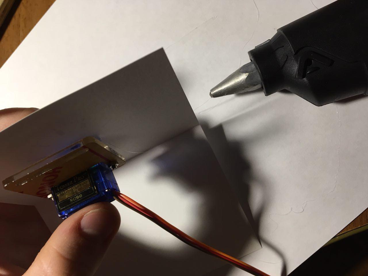
Figure 6. Fit the dial to the body of the servoStep 6. Do the same design on a wooden platform and set the arrow (Fig. 7);

Figure 7. Installation and Assembly hoursStep 7. Use colored wires for connection (Fig. 8);

Figure 8. Connect the servo to the deviceStep 8. Connect the wires to the necessary pins as shown in figure 9;

Figure 9. Wire data to the G5, wire + supply to 5V, leads - power supply to GNDStep 9. Connect the device to the computer using the USB cable C (Fig. 10);
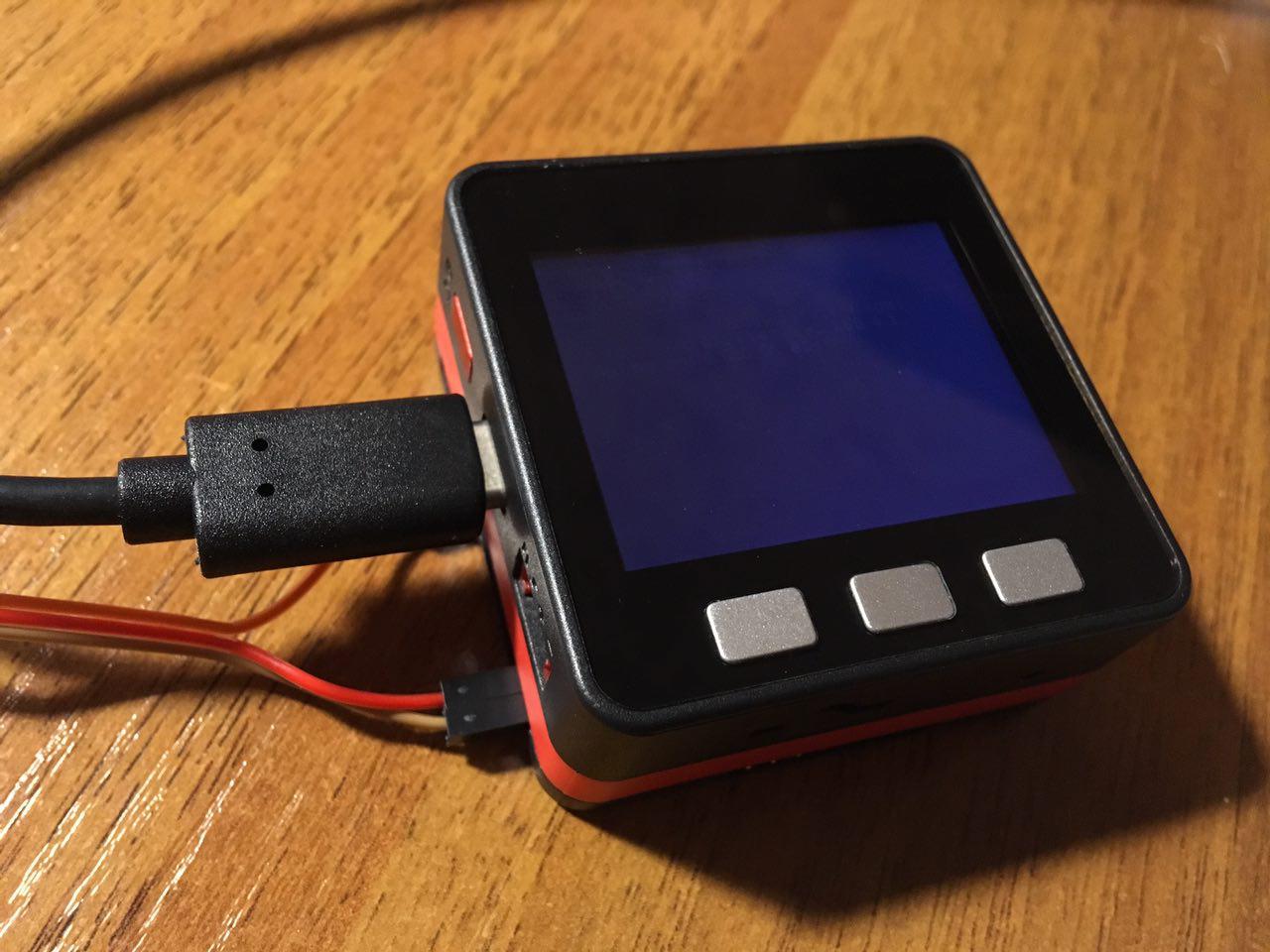
Figure 10. Connecting to a PCStep 10. Create a new project in the Arduino IDE and write the code:
#include <M5Stack.h>

int servoPin = 5;
// default time
int H = 0;
int M = 59;
int clockTable[12][2] = { // calibrate clock table
{28, 157}, {157, 130}, {130, 103}, {103, 79},
{76, 52}, {49, 28}, {28, 9}, {9, 130},
 {130, 103}, {103, 79}, {79, 52}, {52, 28}
};
int S = 0;
unsigned long cMls;
unsigned long pMls = 0;
bool dots = false;

int servoPulse(int angleDegrees)
{
int pulseWidth = map(angleDegrees, 0, 180, 544, 2400);
return pulseWidth;
}

void servoSet(int oldAngle, newAngle, int) {
int pulseWidth;
if (oldAngle == newAngle)
{
return;
}
else if (oldAngle < newAngle)
{
for (int i = oldAngle; i <= newAngle; i++){
pulseWidth = servoPulse(i);
digitalWrite(servoPin, HIGH);
 delayMicroseconds(pulseWidth);
digitalWrite(servoPin, LOW);
delayMicroseconds(20000 - pulseWidth);
}
}
else if (oldAngle > newAngle)
{
for (int i = oldAngle; i >= newAngle; i--){
pulseWidth = servoPulse(i);
digitalWrite(servoPin, HIGH);
delayMicroseconds(pulseWidth);
digitalWrite(servoPin, LOW);
delayMicroseconds(20000 - pulseWidth);
}
}
}

void setH(bool readOnly = false) {
if (!readOnly) H++;
if (H > 11) H = 0;
M5.Lcd.fillRect(80, 110, 70, 42, 0x00);
M5.Lcd.setTextColor(0xfbe4);
M5.Lcd.setTextSize(6);
M5.Lcd.setCursor(80, 110);
servoSet(clockTable[H][0], clockTable[H][1]);
if ((H < 10) && (H != 0)) M5.Lcd.print(0);
M5.Lcd.print(((H == 0) ? 12 : H));
}

void setM(bool manual = false, bool readOnly = false) {
if (!readOnly) M++;
if (M > 59)
{
M = 0;
if (!manual)
{
setH();
M5.Speaker.tone(660);
delay(50);
M5.Speaker.mute();
M5.Speaker.tone(440);
delay(50);
M5.Speaker.mute();
M5.Speaker.tone(820);
delay(50);
M5.Speaker.mute();
}
}
M5.Lcd.fillRect(180, 110, 70, 42, 0x00);
M5.Lcd.setTextColor(0xfbe4);
M5.Lcd.setTextSize(6);
M5.Lcd.setCursor(180, 110);
if (M < 10) M5.Lcd.print(0);
M5.Lcd.print(M);
}

void setS() {
S++;
if (S > 59)
{
S = 0;
setM();
}
if (dots)
{
M5.Lcd.fillRect(150, 110, 29, 42, 0x00);
}
else
{
M5.Lcd.setTextColor(0xfbe4);
M5.Lcd.setTextSize(6);
M5.Lcd.setCursor(150, 110);
M5.Lcd.print(":");
}
dots = !dots;
}

void setup() {
m5.begin();
pinMode(servoPin, OUTPUT);
M5.Lcd.setBrightness(200);

M5.Lcd.setTextColor(0xffff);
M5.Lcd.setTextSize(3);
M5.Lcd.setCursor(65, 20);
M5.Lcd.print("Servo Clock");

M5.Lcd.setTextColor(0x7bef);
M5.Lcd.setTextSize(2);
M5.Lcd.setCursor(55, 60);
M5.Lcd.print("please, setup time");

M5.Lcd.setCursor(60, 215);
M5.Lcd.printf("H");

M5.Lcd.setCursor(250, 215);
M5.Lcd.printf("M");

setH(true);
setM(true, true);
}

void loop() {
cMls = millis();
 if (M5.BtnA.wasPressed()) setH();
if (M5.BtnC.wasPressed()) setM(true);
if ((cMls - pMls) > 1000)
{
pMls = cMls;
setS();
}
m5.update();
}
Step 11. Upload the sketch to the device (Fig. 10.1);

Figure 10.1. Uploading your sketch to the deviceStep 12. After loading the sketch, the unit will restart and will appear on the screen menu;

Figure 11. The display menuStep 13. Set the time using buttons H and M and wait for the arrival of the next hour (Fig. 12);

Figure 12. Watch worksDownload
Video demonstration of the work you can download here https://yadi.sk/i/sOEpVp7r3RkPoY
The sketch can be downloaded here https://yadi.sk/d/1kpt9gH33Rm49M
A file for printing of the dial can be downloaded here https://yadi.sk/d/Dr7CWpnW3Rm53V
-
-
hi,
thank you for your lesson (all lesson).
Very great for me, i m beginer.Have you lesson with bluetooth
thank you
-
@olivier thanks! in future