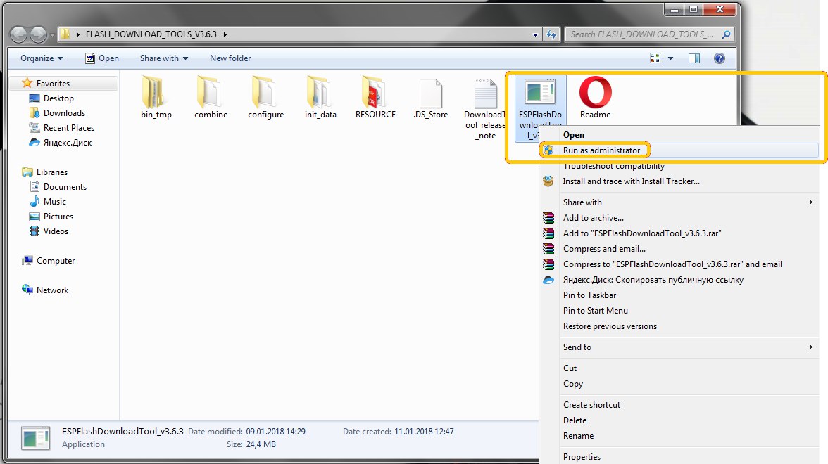
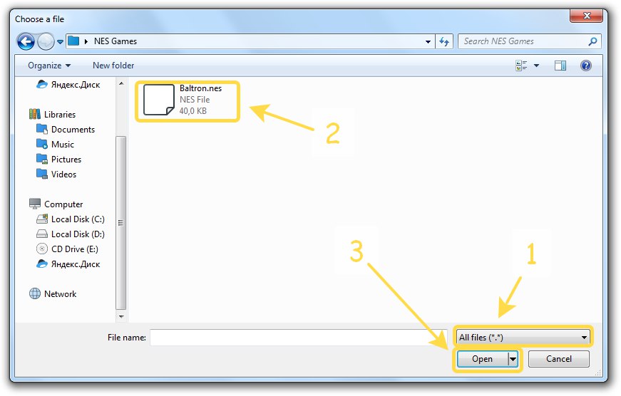
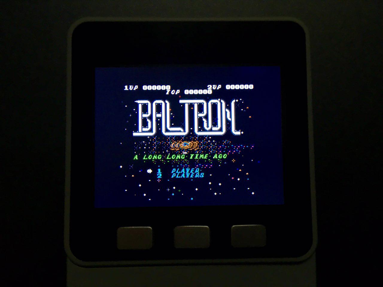
@mikemoy Oh! Sorry. You can download this app here: https://ru.m5stack.com/downloads/Image2Code.exe

Dimi
@Dimi
Posts made by Dimi
-
RE: Lesson 1.2.1. LCD. How to create image array
-
RemoteLoRa – more than ON/OFF
Figure 1
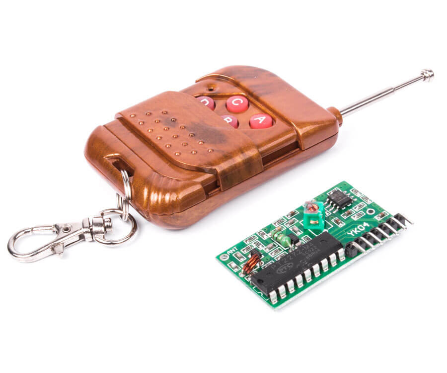
Today in the market you can find a bunch of all kinds of radio remotes. One of the most popular is the model based on IC2262/2272 (Figure 2). The solution is quite suitable for itself, but only in case you do not need feedback, encryption (or addressing) and analog mode.
Figure 2
I wanted to make an improved prototype of such a keyring, which will have in itself those advantages that are not in the existing solutions.
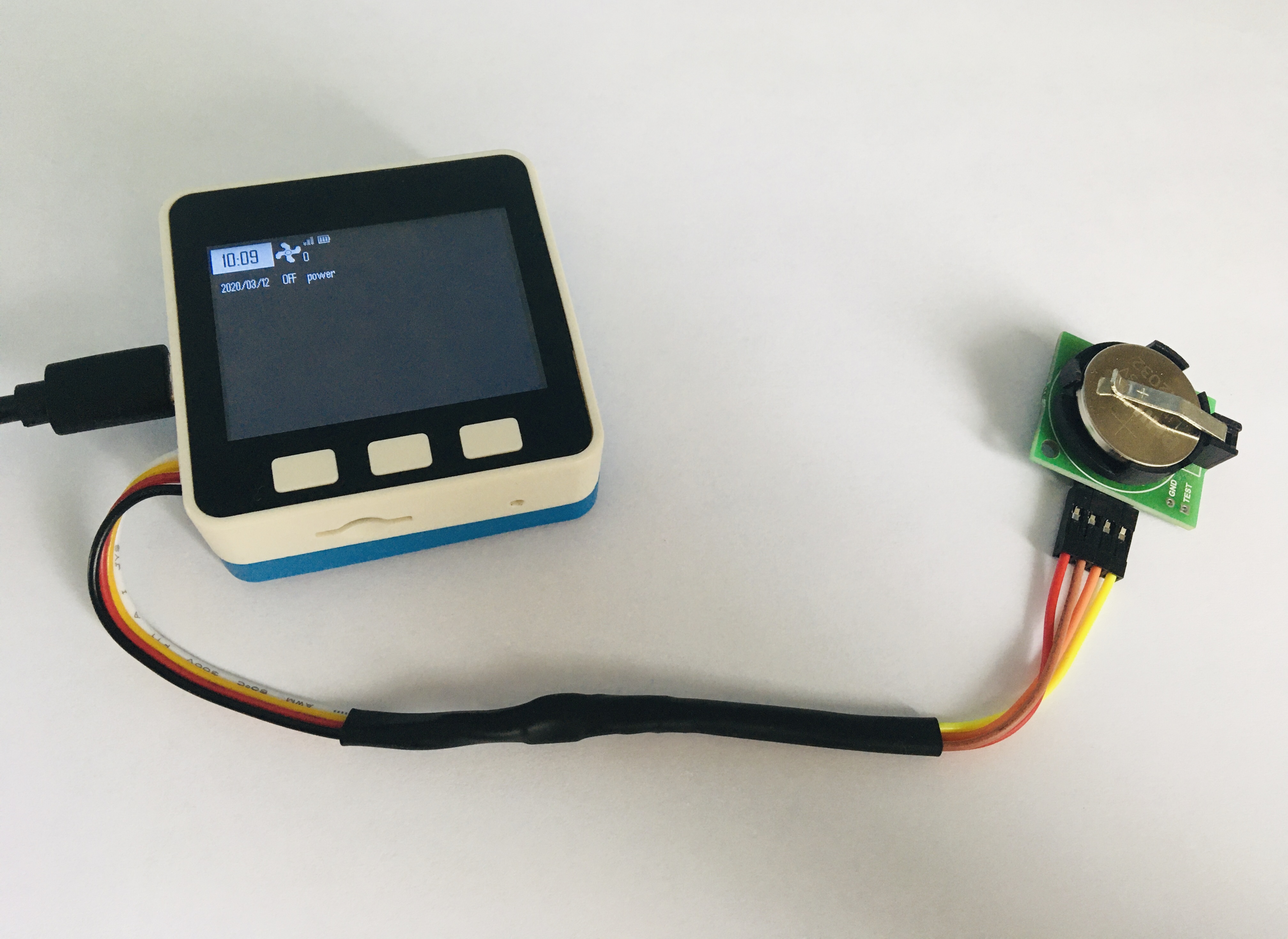
To create a prototype, I use the Base Unit M5Stack BASIC (you can buy here) with the pre-installed LORA Module and connected via I2C real clock time (because Wi-Fi with NTP to knit here will be superfluous).
When you turn on the device for the first time, it suggests choosing the type of connection with the client device - asynchronous or synchronous. If synchronous is selected, the device will wait for the control value from the slave, then signal (triangular icon with an exclamation mark).
It is further proposed to choose the type - digital (HIGH and LOW) or analog (-127 ... + 127). In digital mode, when accessing the slave device, HIGH or LOW will be transmitted alternately, and with an analog counter, increased by one. If an analog type is selected, the device will ask for the minimum and maximum value within which the counter will operate.
Next, the device will ask - will the key be used? (or
call the address whatever you want). If you select a closed lock, the device will wait for the key from the slave. For demonstration purposes, the slave is Arduino Nano with Module Ra-01. When turned on, the Arduino sends a key. This is visible in the video.Next, you can select the icon for the slave (Figure 3).
Figure 3
After you select the icon, you will be asked to select units or qualifying words, such as: "power", "red", "green", "blue", "cold", "warm", "$", " % "," oC "," uV "," mV "," V "," uA "," mA "," A "," uW "," mW "," W "," m / s "," km / H "," ug "," mg "," g "," kg "," mL "," L "," rpm "," dBm "," ". It is important!
After all the steps have been completed, you need to save this configuration by pressing the button A (or C to cancel).
The device will reboot and you will see the clock, date and time, battery charge, signal strength indicator, previously selected slave icon, device serial number to the right of the icon (starts from zero), default value and unit.
To access the slave, press A. To change the slave, press B.
To reboot the device, press C.If you want to remove the device from the list, then press C then B, instead of the slave device icon, the basket and serial number will be displayed. Use B to select the device to be deleted and press A (or C to cancel).
The real-time clock is set by pressing the C key after rebooting the device. You can access the hours, minutes, year, month, and day with the B key, and change the value with the C key. To save, press the A key.
Let's see what happened (YouTube). In this video, Arduino duplicates the received command, and M5Stack finds the control value in it and signals about it.
Source code is available on GitHub
I hope that this project will soon receive a public assessment and will leave the prototype shelf. Thank you very much for your time.
-
GSMout - receive SMS and calls "at home"
Picture 1Today, there are virtually no Internet resources that would not need your phone number. Verification of the number is usually done by receiving an SMS with a code or a call, where the last digits of the number are an argument for confirmation. If you are engaged in business, then you probably came across the fact that in order to perform certain banking operations, you must sign them using the code from SMS. Everything is good when you are in your home region and getting a code is not difficult, the situation is much more complicated if you are in another region where roaming does not work, because your phone or SIM card is not supported by local cellular operators. One of the elegant solutions is this project (Figure 1). In the home region, you leave M5Stack with a SIM card installed, get static IP from the operator, open the port and get access to the log of incoming SMS and calls online from anywhere in the world where there is Internet access.
No modems, but you hold on!
Out of the box in the Base Unit M5Stack there is no built-in modem and there is nowhere to insert a SIM card, so you need to additionally purchase a GSM module (you can select it at link) .
Please, when choosing
make sure that you have no sins behind your backbe especially selective... If you look datasheet on SIM800L, it says so:4.1. Power supply
The power supply range of SIM800L is from 3.4V to 4.4V. Recommended voltage is 4.0V. The transmitting burst will cause voltage drop and the power supply must be able to provide sufficient current up to 2A. For the VBAT input, a bypass capacitor (low ESR) such as a 100 μF is strongly recommended.
Do you understand what I mean? The dropper. My Air, on which I write the code, does not give a current of up to 2 A. We open the braid of the USB-C cable, cut what wire? Red. We connect an external power supply unit to 5 Volts 3 Amperes
so that for sureto the place of the notch. Now, the power of the Basic device will go from an external power source (and everything will be fine - I thought). But the modem did not think so. For him there was too much ~ 4.8 Volts and he screamed in every possible way with his only LED.It was necessary to look for a solution further. The standard Bottom Module has an attractive contact BAT. Class! All! Here is the solution! After all, a lithium-polymer battery is just 3.7 Volts. ESP32 needs 3.3 V. We power the basic device through this contact. One, two, three, multimeter say voltage! Bah! The voltage is again ~ 4.8 Volts. In the Basic device, the power circuit increased it. Method two has gone down in history.
The third method was the most successful. Hot air gun and step-down converter ** LM2596** have done their job (Figure 2).
Figure 2Which pull, captain?
When the hardware problems have passed us, we will create software! Download the project source from the GitHub repository.
At the beginning of the project code there are a couple of lines that you can edit if you want to change the server port
int web_port = 80;
and the web page address of the magazine
String web_mainPage =" GSMout ";
Pay attention to the data folder - files from this folder must be loaded into SPIFFS-memory using the plug-in for Arduino IDE called ESP32 Sketch Data Upload (the plug-in is in [this repository] (https://github.com/me-no-dev/arduino-esp32fs-plugin)), but before that you must add the file (s) of the type myHomeHotspot.wifi, where myHomeHotspot is the name of the Wi-Fi network, and the contents file - password. This is necessary to automatically connect the Core to Wi-Fi.
It works.
At startup, the device connects to a Wi-Fi network, then checks for Internet access, updates the time and date via NTP, and sets up the modem. The corresponding icons are shown on the display, watchCat and the journal web page address are responsible for the icons. When new messages arrive or the icon’s calls become colored and their number is displayed on the right, the counter is reset to zero after the log web page is requested. That's all.
When you open the address indicated on the M5Stack screen, a log is displayed in the browser (Figure 3).
Figure 3I hope this project helps you someday. Special thanks to the author of the article "at-command of the gsm modem sim900" located here.
A video demonstration of the work can be seen here
-
GSMout – приём SMS и звонков "как дома"
Рисунок 1Сегодня практически отсутствуют Интернет-ресурсы, которым бы был не нужен Ваш номер телефона. Верификация номера проходит обычно путём получения SMS с кодом или звонком, где последние цифры номера являются аргументом для подтверждения. Если Вы занимаетесь бизнесом, то наверняка сталкивались с тем, что для совершения тех или иных банковских операций необходимо подписывать их с помощью кода из SMS. Всё хорошо, когда находитесь в домашнем регионе и получить код не составит труда, гораздо сложней ситуация обстоит, если Вы находитесь в другом регионе, где роуминг не работает, т. к. Ваш телефон или SIM-карта не поддерживается местными сотовыми операторами. Одним из элегантных решений является данный проект (рисунок 1). В домашнем регионе Вы оставляете M5Stack с установленной SIM-картой, получаете белый IP у оператора, открываете порт и получаете доступ к журналу входящих SMS и звонков онлайн с любой точки мира, где есть Интернет.
<cut />
Модемов нет, но Вы держитесь!
Из коробки в Базовом устройстве M5Stack нет встроенного модема и вставлять SIM-карту некуда, поэтому необходимо дополнительно приобрести GSM модуль (выбрать можно по ссылке).
Пожалуйста, при выборе
убедитесь, что у Вас нет грехов за спинойбудьте особенно избирательны... Если посмотреть datasheet на SIM800L, то там сказано так:4.1. Power Supply
The power supply range of SIM800L is from 3.4V to 4.4V. Recommended voltage is 4.0V. The transmitting burst will cause voltage drop and the power supply must be able to provide sufficient current up to 2A. For the VBAT input, a bypass capacitor (low ESR) such as a 100 μF is strongly recommended.
Понимаете о чём я? "Капельница". Мой Air, на котором я пишу код, не отдает ток до 2 А. Вскрываем оплётку USB-C кабеля, перерезаем какой провод? Красный. Подключаем внешний блок питания на 5 Вольт 3 Ампера
чтоб уж навернякав место надреза. Теперь питание Базового устройства будет идти от внешнего источника питания (и всё станет хорошо - подумал я). Но модем так не думал. Для него было слишком много ~4,8 Вольт и он всячески "кричал" своим единственным светодиодом.Надо было искать решение дальше. У стандартного Завершающего модуля есть привлекательный контакт BAT. Класс! Всё! Вот оно решение! Ведь литий-полимерный аккумулятор как раз на 3,7 Вольта. ESP32 надо 3.3 В. Запитываем Базовое устройство через этот контакт. Раз, два, три, мультиметр напряжение говори! Бах! Напряжение опять ~4,8 Вольт. В Базовом устройстве схема питания его повысила. Способ два ушёл в историю.
Способ третий оказался самым успешным. Термофен и понижающий преобразователь LM2596 сделали своё дело (рисунок 2).
Рисунок 2За что дёрнуть, капитан?
Когда аппаратные проблемы нас миновали, создадим программные! Скачиваем исходник проекта с GitHub-репозитория.
В начале кода проекта есть пара строчек, которые Вы можете отредактировать, если захотите изменить порт сервера
int web_port = 80;
и адрес веб-страницы журнала
String web_mainPage = "GSMout";
Обратите внимание на папку data – файлы из этой папки необходимо загрузить в SPIFFS-память с помощью плагина для Arduino IDE, который называется ESP32 Sketch Data Upload (плагин находится в этом репозитории), но перед этим Вы должны добавить туда файл(ы) типа myHomeHotspot.wifi, где myHomeHotspot - имя Wi-Fi-сети, а содержимое файла – пароль. Это необходимо для автоматического подключения Базового устройства к Wi-Fi.
Это работает.
При запуске устройство подключается к Wi-Fi-сети, затем проверяет наличие доступа к Интернет, обновляет время и дату по NTP, настраивает модем. На дисплее отображаются соответсвующие иконки, за иконки отвечает watchCat и адрес веб-страницы журнала. Когда приходят новые сообщения или звонки иконки становятся цветными и справа отображается их число, счётчик обнуляется после запроса веб-страницы журнала. На этом всё.
При открытии адреса, указанного на экране M5Stack, в браузере отображается журнал (рисунок 3).
Рисунок 3Надеюсь, Вас данный проект выручит когда-нибудь. Особая благодарность автору статьи "at-команды gsm модема sim900", расположенной здесь.
Видео с демонстрацией работы можно посмотреть здесь
-
ESP32 and the SPIFFS file system
SPIFFS – (Serial Peripheral Interface Flash File System). In simple words: there is an ESP32 microcontroller (figure 1), it has a built-in rewritable non-volatile NOR memory, which stores: settings (Preferences), bootloader (Bootloader), firmware (compiled sketch), file system (SPIFFS) and something else, such as "over-the-air" updates (OTA).
Figure 1. Functional block diagram of the ESP32 microcontroller
NOR-memory is a type of non-volatile rewritable memory, which has a sufficiently high read speed, relatively low write and stream speed, in comparison with the type of memory NAND. It is almost impossible to meet NOR-memory of a large volume, usually it is limited to 128 MBytes. In the case of ESP32– 4 MB.
To date, SPIFFS has some drawbacks
shortcomings, including: lack of folder support; no real-time stack, so the same operation may take different time; lack of ability to find and fix broken blocks. If the listed shortcomings are not critical for You, then we will continue to read the following paragraph.Let's talk about using
Unfortunately, out of the box, the memory of the microcontroller is not marked up under SPIFFS, in order to mark up, you need to use the plugin ESP32FS for the Arduino IDE development environment.
After the plugin is downloaded – it must be installed:
- Make sure you have the latest version of the Arduino IDE and driver for Your device on ESP32. I have M5Stack drivers CP210X I download on this link;
- Copy the downloaded tool folder with the plug-in attached to it to the /Arduino/tools/ESP32FS folder/;
- In macOS the folder is located at ~/Documents/Arduino/;
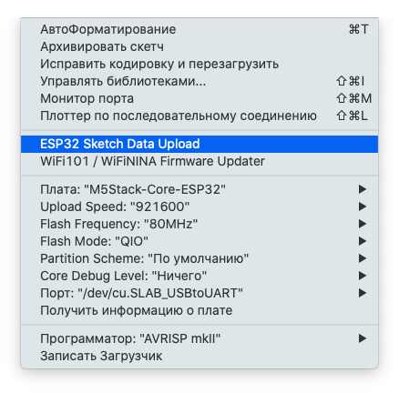
- Restart the computer and provrete in the development environment in the menu Tools (Tools) appears item ESP32 Sketch Data Upload (figure 2) - so you have done everything correctly;
Figure 2. Menu Tools
- Note the data folder next to the sketch. All files located in this folder will be loaded into the device's memory when formatting;
- Feel free to select the specified item and wait for the end of formatting the memory area. Please note that other memory areas will not be affected, which means that the firmware will remain in the device's memory and will work. Similarly with the sketch, when it is compiled into the firmware and loaded into the device-the file system will not be affected.
If you want comfort
-
If you want to touch files and see information about free space, then download the sketch BRIDGE and stitch your device with it.
-
Also download
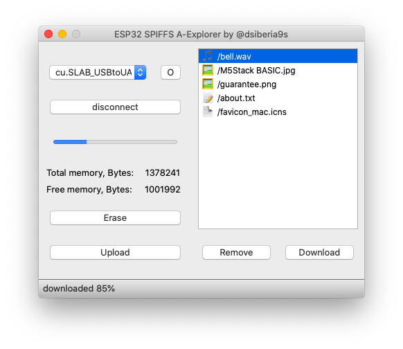
and compilecross-platform file Manager A-Explorer (figure 3). On GitHub the binary files are in the realize folder.Figure 3, a. A-Explorer File Manager for macOS
Figure 3, b. A-Explorer File Manager for Windows
This file Manager allows you to find information about free space, upload/download / delete files. There is an indication of the progress of the operation.
As you can see in figure 3, the plugin marked up approximately 1.38 MB of memory under SPIFFS.
Who is this BRIDGE?
BRIDGE is a sketch, and above all a function of the same name that works with the SPIFFS file system and A-Explorer is a graphical shell for it. The latter sends a particular command, and this function processes it on the device itself using the FS and SPIFFSlibraries. Let's see what's interesting about these libraries.
How to use public methods of the SPIFFS class:
-
Bool begin method(bool formatOnFail=false, const char * basePath= "/spiffs", uint8_t maxOpenFiles=10). This method attempts to initialize an instance of the class. The first argument is true or false, in case it is worth formatting the background system if the file system is not formatted. The second argument takes the path where the root of the file system will be located. The third argument will determine the number of files opened at the same time. It is better to leave the last two parameters defaulted and not change them. If there is no file system (the plugin above was not used). that function will return a lie.
-
The bool format() method will check whether the file system is formatted-returns true, in the primitive case-false.
-
Size_t totalBytes() method. This method returns size_t-the number of total Bytes allocated for the file system.
-
Size_t usedBytes() method. This method returns size_t-the number of Bytes used in the file system.
-
Void end() method. This method leads to the deinitialization of this class. After calling this method, it is pointless to call other methods.
In this class, everything, nothing particularly interesting. Let's go to the class FS and see what we can use from there.
-
The first thing that catches your eye is the initializer method of the bool begin() class. This method does not require arguments and there is no need to call it, because we will use the following method immediately.
-
Method File open (const char* path, const char* mode) and its brother File open(const String& path, const char* mode). These methods take two arguments each: the first is a character pointer and a string pointer to the file path, and the second is an open mode, which can be the following constat:
FILE_READ – open read-only;
FILE_WRITE – open for writing only;
FILE_APPEND – open for additional recording.
After we have opened the file, we can now perform any operations on it.
- The size_t write(uint8_t) method allows you to write a single 8-bit unsigned integer to the end of the file.
- The size_t write method (const uint8_t *buf, size_t size) allows you to write a number of unsigned integers of the specified length in the second argument.
- The int available() method counts the number of characters from the end to the pointer.
- The int read() method reads a single character from the file and returns it as an integer, with the cursor shifted one right.
- The size_t readBytes(char *buffer, size_t length) method reads characters to the buffer, the pointer to which is received by the first argument, and the number of characters passed by the second argument. Returns the number of characters used.
- The String readString () method reads a string from a file.
- The int peek() method works similarly to the int read () method, only the cursor remains in place.
- The bool seek(uint32_t pos, SeekMode mode) and bool seek(uint32_t pos, SeekMode mode) methods set the cursor to the specified location. The first argument passes the position, and the second rule (SeekSet - set the cursor). If successful-returns true, otherwise-false.
- The size_t position() method returns the cursor position.
- The size_t size() method returns the file size in Bytes.
- The const char * name() method returns the file name.
- Const char * fullName() method with full path.
- The bool isFile() method returns true if the open object is a file. Otherwise, it's a lie.
- The bool isDirectory() method returns true if the open object is a folder. Otherwise, it's a lie.
- The File openNextFile() method returns a pointer to the next file in the root, otherwise NULL.
- The method bool exists(const char* path) and bool exists(const String& path) takes the full file name as an argument, and if such a file exists, it returns true, otherwise it is false.
- The bool remove(const char* path) and bool remove(const String& path) methods attempt to delete the file whose name is passed as arguments. If successful, returns istrina, otherwise-a lie.
- Method bool rename(const char* pathFrom, const char* pathTo) and bool rename (const String& pathFrom, const String& pathTo); takes the full file name first arguments, and the second full new file name and rename.
Yes, you can take this function and run it in a separate thread in any other sketch 😉
Thank you very much for your time! I will be glad if this article will benefit you.
List of references and (or) sources:
- SPIFFS Filesystem
- Working with the file system in the addon ESP8266 in the Arduino IDE
- Arduino ESP32 filesystem uploader
-
Storing settings in the memory of the Core
Hello! If you are fortunate enough to hold the ESP32 microcontroller in your hands (I was more fortunate and have M5Stack in my hands) from the Chinese company ESPRESSIF, then this post may be useful.
There is a situation when it is necessary to save some parameters in non-volatile memory (for example: count the number of times the device is turned on for the entire time or save the Wi-Fi settings). This can be done with ease using the Preferences library.
We declare an instance of the Preferences class, and there we will see ...
The first thing we need to do is create a keychain by calling the begin method with a pair of arguments (but only with the first one): the name of the keychain and the read-only flag.
To save a string value in memory, you need to pass the key and the value itself to a method whose name consists of two parts: the first is put and the second is the type name, for example: String. Everything is clear and understandable. True, there are still "raw" bytes
without roasting, to which no one wants to assign a type. In this case, the method also takes the third argument with the number of these bytes. With this procedure, everything seems to be.After the value has been written, you can read using the method (whose name is similar to the previous one), where the first part will be get. This method returns the value for the key of the corresponding type. Remember the byte case? If you don’t know (or don’t remember) how many bytes are on the key, then pull the getBytesLength method with a single argument - the key, it will calculate everything and return the amount to size_t.
If you want to remove a certain key from the keychain, then give it the only argument to the remove method.
Do you want to bring a real marafet and clear the whole bunch? Call the clear method without any arguments!
When you wish to complete the work with the bundle, call the end method without any arguments.
In general, the following types are supported: Char, UChar, Short, UShort, Int, UInt, Long, ULong, Long64, ULong64, Float, Double, Bool, String and Bytes.
I understand that I want
somethingcode, so here is a sketch. A sketch counts the number of turns on the device and displays it on the display:#include <M5Stack.h> #include <Preferences.h> Preferences preferences; const char* key = "OnOff"; uint32_t count; void setup() { m5.begin(); preferences.begin("MyKeyChain"); count = preferences.getUInt(key); preferences.putUInt(key, count + 1); M5.Lcd.setTextSize(3); M5.Lcd.setTextColor(TFT_WHITE); M5.Lcd.println("Hello, Habr!"); M5.Lcd.setTextSize(2); M5.Lcd.println("M5Stack Turned On:"); M5.Lcd.setTextSize(3); M5.Lcd.setTextColor(TFT_RED); M5.Lcd.println(count); M5.Lcd.setTextColor(TFT_WHITE); M5.Lcd.setTextSize(2); M5.Lcd.println("times"); } void loop() { }
Library link.
-
Showing numbers with the flashes of light
Hello! If a situation arises when it is necessary to find out the humidity and temperature, but the display is not possible to use for some reason.
List of reasons:
- expensive;
- afraid of moisture;
- too lazy to solder;
- a small print that is not visible at all;
- important aesthetics and minimalism;
- all listed together.
In this case, there is an excellent reason to use the color approach to displaying information. Everything would be fine, but the primary colors are completely worthless - some seven (from the rainbow). Can you distinguish between light blue and blue or yellow from orange? What to do? Remove such strange colors! Leave: Red, Yellow, Green, Blue, Purple and White (unexpectedly, yes?). How much did it work? 6. And there are 10 digits, and even a minus for negative numbers, a floating point and a separator. We will be smart and make a flasher! Violet - it will be 5, and six it will be 5 + 1, and 1 will be Red. Just fit. Huh! Table 1 shows the colors for the corresponding characters.
Table 1
Number (or char) Color (s) Zero blink VIOLET One light up RED Two light up YELLOW Three light up GREEN Four light up BLUE Five light up VIOLET Six blink VIOLET / RED Seven blink VIOLET / YELLOW Eight blink VIOLET / GREEN Nine blink VIOLET / BLUE Negative (-) blink WHITE / RED Floating point (.) blink WHITE Line feed (\n) light up WHITE Primary you need download and connect the library. Then declare a custom callback function void callback (int, int, int) R, G, B - channels (from 0 to 255), which will access the hardware (light up the LED). Call the lightf function, where the first argument will be a pointer to this same callback function, then a line with a format that is completely analogous to printf and any number of arguments. Remember to use the newline character \ n, after each qualifier in the format string.
At my fingertips lies the Base Unit M5Stack FIRE with built-in Neopixel panels, for testing, as nothing else is better. You can watch a video demonstrating a sketch showing the Pi number with an accuracy of 6 decimal places (YouTube) here.
Thanks!
Download library (GitHub) here
-
Lesson 23. M5CAMERA. Introduce
The purpose of this lesson
Hi! Today we'll meet M5CAMERA (figure 1).
Figure 1
This tutorial will teach you how to use the camera with a web browser.
Short help
- Purpose: used for video surveillance in real time
- Scope: agriculture, science and home life
- Connection interface: Wi-Fi, I2C (Groove), PDM, GPIO, USB Type C
Supply voltage: 5 V - Compatibility: any modern web browser as a client
- Form factor: LEGO compatible
Brief overview
M5CAMERA is the original decision to broadcast images in real time, created by a team of developers M5STACK. This device does not need settings and complex software (figure 1.1).
Figure 1.1
The front panel is centered with the camera lens. To the right of the lens there are holes under which there is a power LED. Below, under the lens, is the M5 logo. On the left side panel there is a button to restart the device. On both sides there are LEGO - compatible holes for the bushings for mounting the legs (figure 2).
Figure 2
There is a sticker with tips on the front side of the device. On the bottom side panel there are I2C (Groove) and USB Type C connectors one after another. The front panel and the front panel are partially connected by means of slot latches and fixed by screws of size M5 (figure 2.1).
Figure 2.1
The heart of this device is the ESP32 module from ESPRESSIF. You can additionally purchase and connect motion sensors (I2C), temperature sensors (I2C), microphone (PDM), LEDs (GPIO), battery. The "eye of the device" is an OV2640 camera with a resolution of 2 Megapixels (figure 2.3).
Figure 2.3
Note: do not attempt to adjust the focus of the camera by rotating the lens, otherwise it will damage the camera loop (figure 3).
Figure 3
Let's start!
Connect the camera to a power source (such as a USB cable). Wait for the red power LED to glow. Good. Now use your smartphone / tablet / computer to connect wirelessly to the access point that the camera has created automatically. Go to Settings (figure 4).
Figure 4
Refer to the wireless Wi-Fi settings section (figure 4.1).
Figure 4.1
Your device should find the wireless network M5Cam-test. Connect to this network (figure 4.2).
Figure 4.2
Good! Now open any new browser and go to http://192.168.4.1 (figure 5 - 5.2).
Figure 5
Figure 5.1
Figure 5.2
Downloads
There is nothing in this tutorial ;)
Demo
There is nothing in this tutorial ;)