Sorry it took me so long answering this question. I have been in contact with @Alf, and there seems to be a problem with the Adafruit_TCS34725.h library used for the M5Stack flow/blockly code. Here are the results and an instruction how to fix the measurements in order measuring (and displaying) reasonable data.
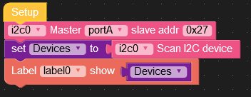
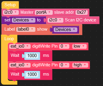
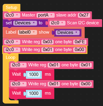
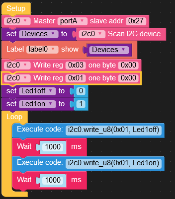
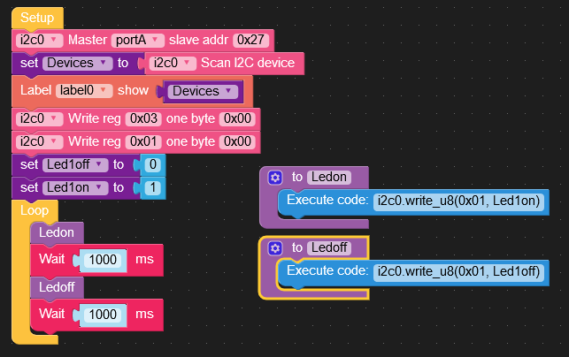
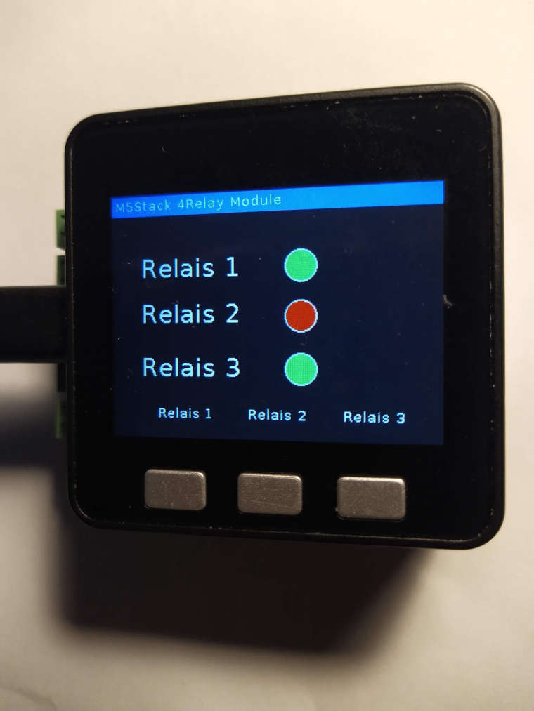
As described in the example library for the color sensor hub I downloaded the following code for the flow/blockly environment to my M5Stack with the color hub attached:
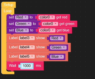
Then I measured a piece of bright white paper and then a piece of dark black paper. The results of the readings of tmy measurement were:
black => red: 176 green: 231 blue: 255
white => red: 192 green: 235 blue: 255
If the color HUB program would work correctly, the readings shoul be 0,0,0 for black and 255,255,255 for white !
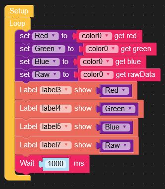
If you add a variable Rawdata to the program and display the readings in a label, 4 additional values are displayed: the raw readings for the 4 sensors of the TCS3472x in the color sensor HUB (white, red, green, blue). The readings for the sensors raw readings now were:
black => white: 18270 red: 3000 green: 6528 blue: 7852
white => white: 65535 red: 13892 green: 25465 blue: 30070
Doing a bit of math using the raw data values you can then make the M5Stack display the correct (and expected) values for the RGB measurements.
Because the leds of the Color Hub are always on, as @ajb2k3 correctly stated in his response, the sensor is affected by stray light from the leds By the way, M5Stack should make the Color sensor HUB casing black instead of white, diminishing the effect of stray light and also switching off the leds, when you are not taking any measurements.
Putting the values read above into new values for the measurement into new values you can then correct the values of a color measurement in 4 Steps:
Step 1:
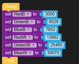
You will have to enter the values of raw measurement you measured above for the RGB into new variables (you don't need the datas for clear):
Raw values for black: RedB=3000 , GreenB=6528 , BlueB=7872
Raw values for white: RedW=13892, GreenW=25465 , BlueW=30070
Step 3:
Correct the white measurement datas subtracting the black data (correction for zero + stray light) . This corresponds to the range of measurements between black(minimum) and white (maximum):
RedR=RedW-RedB , GreenR=GreenW-GreenB, BlueR=GreenW-GreenB

Step 4:
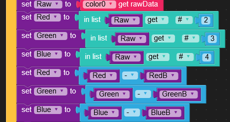
Do the same for your measured values:
Read the raw data for Red, Green, Blue (#2,3,4 of the Raw data list) and put them into variables for Red,Green,Blue. Subtract the values of black readings for the values of Red, Green, Blue
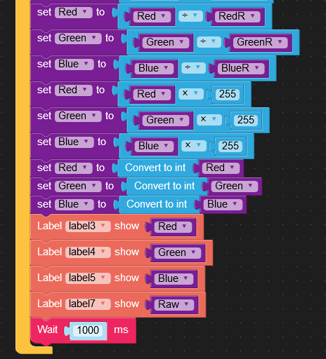
Step 5: Normalize the values
In a normalized environment for color measurements the values for Red, Green, Blue should be in the range 0-255 corresponding to 0,0,0 for black and 255,255,255 for white
So, for each color, you have to divide the values of the corrected mesurements by dividing the values of their corresponding ranges and the multplying the results by 255. In addition, you have to display the values as integers. (As alternative, you can multiply them by 100, then you get a measurement of 0-100% ).
This program shows the basic steps. I have used this procedure to determine the colors of smarties and building a smarties sorting machine together with @Alf using a 5MStack, the I2C color sensor HUB and 2 servos.
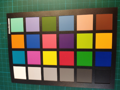
Another project I will have will be implementing a precise RGB multi-point-calibration. In the example above, I assumed the color sensors for RGB to have a linear response curve. I reality that isn't the case. In the multi-point-calibration, as mentioned in the TCS_3472x data sheets explaining the calibration procedure , I will use a datacolor Spydercheckr24 color chart.
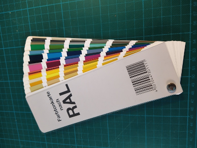
A last project I have, will be using the M5Stack with the color sensor Hub first calibrating and then identifying the 213 classic RAL colors. The corresponding calibration table for the RGB values together with their RAL names will be stored on the microSD card of the M5Stack. In the measurement mode the RAL numbers, the corresponding names and RGB values will be displayed on the M5Stack display. Excel tables with Ral numbers, color names in different languages and their corresponding RGB values are available online, can be downloaded and converted to csv files before storing them on the M5Stack microSDcard. I will use the RAL shade map for calibration:
Because the measurement may be varying with temperature and from sensor to sensor I made 2 improvements to my program:
1: Take 10 measurements and display the mean RGB
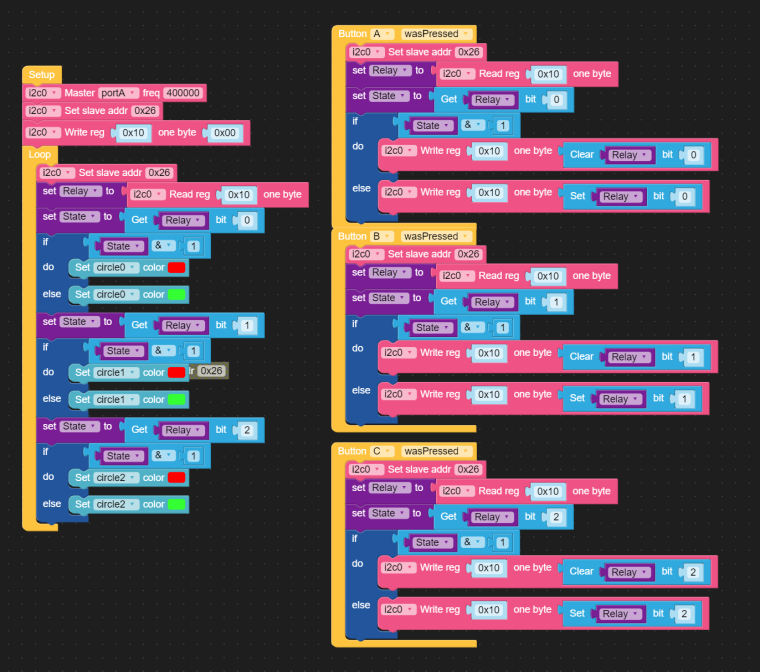
2: By pressing a Button on the M5Stack you can recalibrate the standard values for black and white with a piece of black and white paper and store them for RedB, GreenB, BlueB and RedW, GreenW and BlueW. That way, you don't have to rewrite and download your programm when you start the programm later or if you change the sensor.