Navigation

    M5Stack Community

    • Register
    • Login
    • Search
    • Categories
    • Recent
    • Tags
    • Popular
    • Users
    • Groups
    • Search
    1. Home
    2. Dimi
    3. Best
    • Continue chat with Dimi
    • Start new chat with Dimi
    • Flag Profile
    • Profile
    • Following
    • Followers
    • Blocks
    • Topics
    • Posts
    • Best
    • Groups

    Best posts made by Dimi

    • Lesson 6.1. Speaker. MP3 player

      The purpose of this lesson

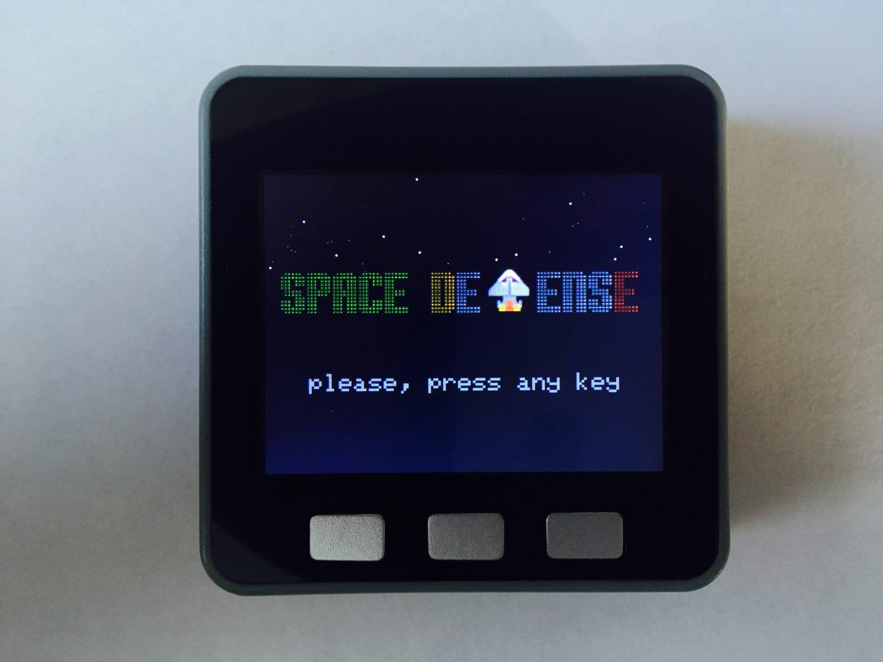
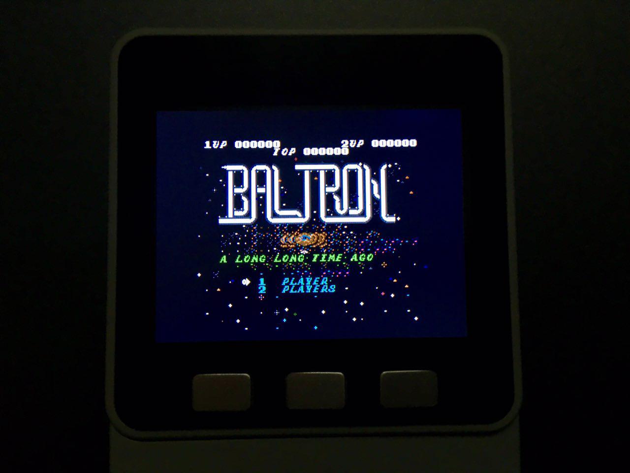
      Hi! Today we will learn how to play audio files of MP3 format using the built-in DAC. Write a simple player (Fig. 1).

      Figure 1. Welcome screen

      Brief theory

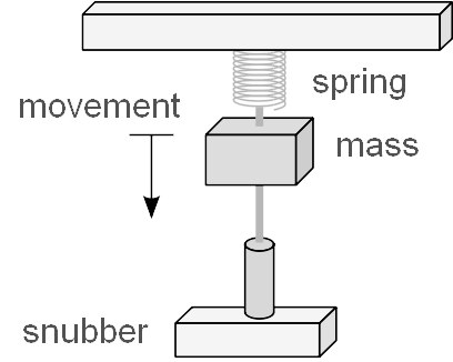
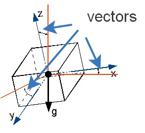
      Digital-to-analog Converter (DAC) – a device for converting digital (usually binary) code into an analog signal (current, voltage or charge). Digital-to-analog converters are the interface between the discrete digital world and analog signals. The signal from DAC without interpolation on the background of an ideal signal is shown in figure 2.

      Figure 2

      In M5STACK the DAC outputs correspond to the 25 and contacts 26 (Fig. 2.1).

      Note that the built-in speaker is connected to 25 pins in parallel. 26 the contact is free and can be used as a linear output. By default, both contacts are enabled, use AudioOutputI2S for configuration

      Figure 2.1

      MP3 audio of the third level, developed by a team of MPEG file format to store the audio information. MP3 is one of the most common and popular digital audio encoding formats. It is widely used in file sharing networks for evaluation download of music. The format can be played in almost all popular operating systems, on most portable audio players, and is supported by all modern models of the music centers and DVD players.

      More information on the Wiki: https://en.wikipedia.org/wiki/MP3

      The development of libraries for ESP32 and ESP8266 to work with popular audio formats, including MP3, is the user GitHub earlephilhower https://github.com/earlephilhower, reference to the library https://github.com/earlephilhower/ESP8266Audio

      List of components for the lesson

      • M5STACK;
      • USB-C cable.

      Begin!

      Step 1. Draw a sketch

      Draw a sketch of our player (Fig. 3). The name of the previous, current and next track will be displayed at the bottom of the screen. The name of the current track will be made black standard font size 3. The side tracks will be grayed out in standard size 2 font. In the center of the screen will be a time line of gray color, which will move the red label. In the upper right corner add four gray pillars that mimic the sound spectrum. The album cover will be located in the left corner.

      Figure 3. Sketch of the project

      Step 2. Logotype

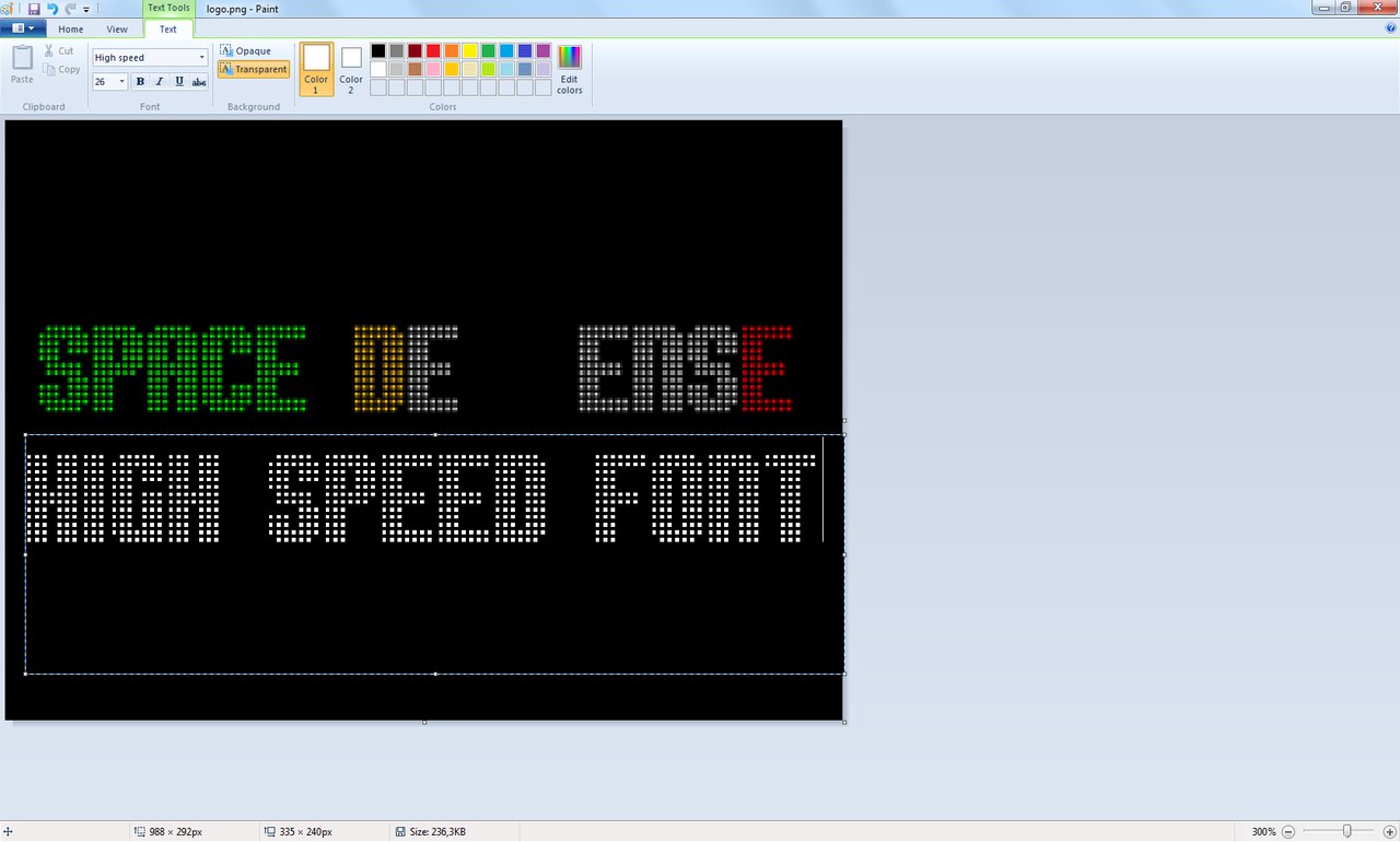
      Let's use the standard graphical editor to make a logo (Fig. 3.1), which will be displayed on the screen when you turn on the device.

      Figure 3.1. The logo of the player

      Don't forget to convert and connect:

      extern unsigned char logo[];
      

      Let's draw our logo from the drawGUI () function of setup():

      void drawGUI() {
        M5.Lcd.drawBitmap(0, 0, 320, 150, (uint16_t *)logo);
        M5.Lcd.setTextColor(0x7bef);
        drawTrackList();
        while (true)
        {
          if (m5.BtnB.wasPressed())
          {
            M5.Lcd.fillRect(0, 0, 320, 240, 0x0000);
            M5.Lcd.fillRoundRect(0, 0, 320, 240, 7, 0xffff); 
            drawTrackList();
            break; 
          }
          m5.update();
        }
      }
      

      Please note that I use the design to work with the SD card-I told about it in the 5th lesson.

      void setup(){
        M5.begin();
        WiFi.mode(WIFI_OFF);
        M5.Lcd.fillRoundRect(0, 0, 320, 240, 7, 0xffff);
        M5.Lcd.setTextColor(0x7bef);
        M5.Lcd.setTextSize(2);
        M5.Lcd.drawBitmap(30, 75, 59, 59, (uint16_t *)timer_logo);
        M5.Lcd.setCursor(110, 90);
        M5.Lcd.print("STARTING...");
        M5.Lcd.setCursor(110, 110);
        M5.Lcd.print("WAIT A MOMENT");
        if (!SD.begin())
        {
          M5.Lcd.fillRoundRect(0, 0, 320, 240, 7, 0xffff);
          M5.Lcd.drawBitmap(50, 70, 62, 115, (uint16_t *)insertsd_logo);
          M5.Lcd.setCursor(130, 70);
          M5.Lcd.print("INSERT");
          M5.Lcd.setCursor(130, 90);
          M5.Lcd.print("THE TF-CARD");
          M5.Lcd.setCursor(130, 110);
          M5.Lcd.print("AND TAP");
          M5.Lcd.setCursor(130, 130);
          M5.Lcd.setTextColor(0xe8e4);
          M5.Lcd.print("POWER");
          M5.Lcd.setTextColor(0x7bef);
          M5.Lcd.print(" BUTTON"); 
          while(true);
        }
        if (!createTrackList("/"))
        {
          M5.Lcd.fillRoundRect(0, 0, 320, 240, 7, 0xffff);
          M5.Lcd.drawBitmap(30, 75, 59, 59, (uint16_t *)error_logo);
          M5.Lcd.setCursor(110, 70);
          M5.Lcd.print("ADD MP3 FILES");
          M5.Lcd.setCursor(110, 90);
          M5.Lcd.print("TO THE TF-CARD");
          M5.Lcd.setCursor(110, 110);
          M5.Lcd.print("AND TAP");
          M5.Lcd.setCursor(110, 130);
          M5.Lcd.setTextColor(0xe8e4);
          M5.Lcd.print("POWER");
          M5.Lcd.setTextColor(0x7bef);
          M5.Lcd.print(" BUTTON");
          while(true);
        }
        drawGUI();
        play('m');
      }
      

      Step 3. Adding libraries

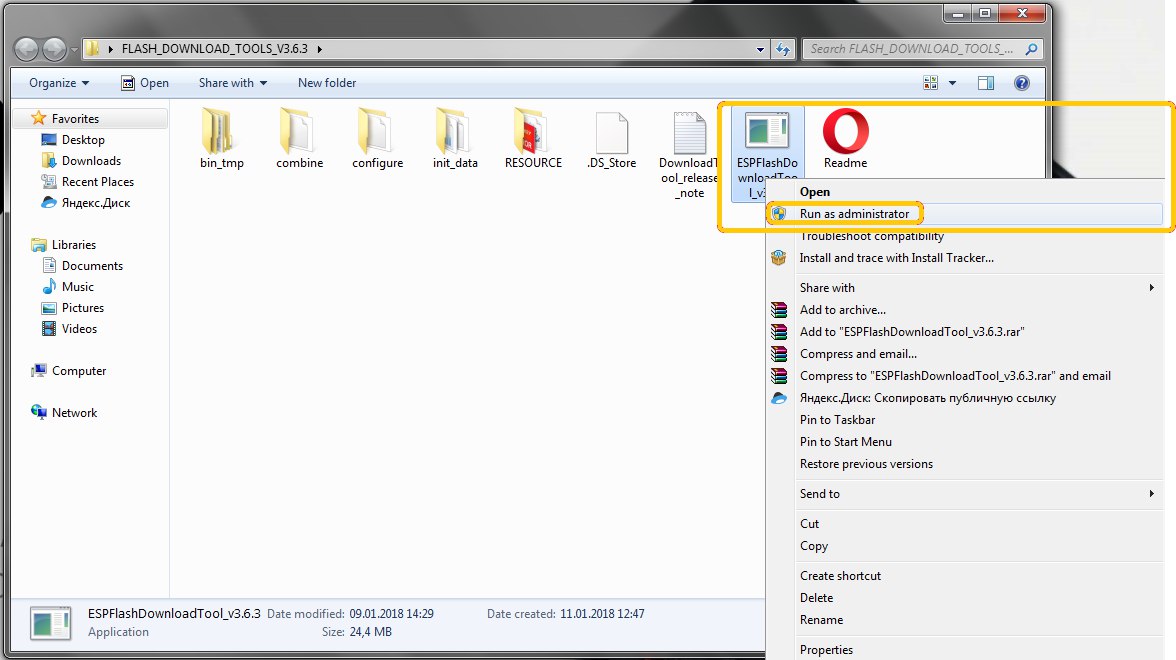
      To use other libraries, you need to add it. You can download it in the appropriate paragraph in the section Download -> Library. In order to add a library you need to launch Arduino IDE select the menu section Sketch -> Include Library -> Add .ZIP Library... (rice. 4, 4.1).

      Figure 4. Adding a library in the Arduino IDE

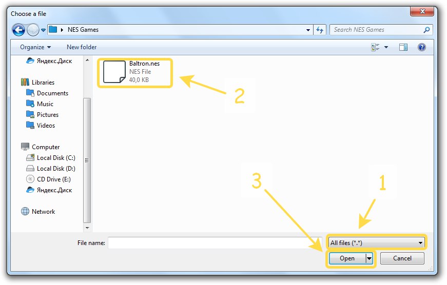
      Figure 4.1. Required libraries into a ZIP-archive

      When libraries are added, you can attach them to a new project:

      #include <M5Stack.h>
      #include <WiFi.h>
      #include "AudioFileSourceSD.h"
      #include "AudioFileSourceID3.h"
      #include "AudioGeneratorMP3.h"
      #include "AudioOutputI2S.h"
      

      Step 4. Use the engine. The case for MP3

      Don't ask "what is it for?"- we'll know it later:

      AudioGeneratorMP3 *mp3;
      AudioFileSourceSD *file;
      AudioOutputI2S *out;
      AudioFileSourceID3 *id3; 
      bool playing = true;
      

      Step 5. Make a playlist

      Let's make a structure containing fields: label (path to mp3-file, the same track name), timePos - time (memory area) on which the track is paused, pointers to neighboring tracks left and right:

      struct Track
      {
        String label;
        int timePos;
        Track *left;
        Track *right;
      };
      

      Declare a dynamic list, in fact, our playlist:

      Track *trackList;
      

      To create a playlist, let's write a simple function that takes as an argument the path where MP3 files are located. If nothing is found, the function returns false:

      bool createTrackList(String dir) {
        int i = 0;
        File root = SD.open(strToChar(dir));
        if (root)
        {
          while (true)
          {
            File entry =  root.openNextFile();
            if (!entry) break;
            if (!entry.isDirectory())
            {
              String ext = parseString(cntChar(entry.name(), '.'), '.', entry.name());
              if (ext == "mp3") 
              {
                i++;
                Track *tmp = new Track;
                tmp->label = entry.name();
                tmp->timePos = 0;
                tmp->right = tmp; 
                if (trackList == NULL)
                {
                  tmp->left = tmp;
                  trackList = tmp;
                }
                else
                {
                  tmp->left = trackList;
                  trackList->right = tmp;
                  trackList = trackList->right;
                }
              }
            }
            entry.close();
          }
          if (i > 1)
          {
            do
            {
              trackList = trackList->left;
            } while(trackList != trackList->left);
          }
          root.close();
        }
        if (i > 0)
          return true;
        return false;
      }
      

      Note that the leftmost and rightmost tracks are self-contained, not NULL

      Step 6. Tracklist drawing is easy!

      String labelCut(int from, int to, String str) {    
        String tmp = str.substring(1, posChar(str, '.'));
        if (str.length() > to)
          tmp = tmp.substring(from, to);
        return tmp;
      }
      
      void drawTrackList() {
        M5.Lcd.fillRect(0, 130, 320, 75, 0xffff);
      
        if (trackList->left != trackList)
        {
          M5.Lcd.setTextSize(2);
          M5.Lcd.setTextColor(0x7bef);
          M5.Lcd.setCursor(10, 130);
          M5.Lcd.print(labelCut(0, 22, (trackList->left)->label));
        }
       
        M5.Lcd.setTextSize(3); 
        M5.Lcd.setTextColor(0x0000);
        M5.Lcd.setCursor(10, 155);
        M5.Lcd.print(labelCut(0, 16, (trackList->label)));
      
        if (trackList->right != trackList)
        {
          M5.Lcd.setTextSize(2);
          M5.Lcd.setTextColor(0x7bef);
          M5.Lcd.setCursor(10, 185);
          M5.Lcd.print(labelCut(0, 22, (trackList->right)->label));
        }
      }
      

      Step 7. Timeline

      unsigned long drawTimeline_previousMillis = 0;
      void drawTimeline() {
        currentMillis = millis();
        if (currentMillis - drawTimeline_previousMillis > 250)
        {
          int x = 30;
          int y = 110;
          int width = 260;
          int heightLine = 2;
          int heightMark = 20;
          int widthMark = 2;
          int yClear = y - (heightMark / 2);
          int wClear = width + (widthMark / 2);
          
          drawTimeline_previousMillis = currentMillis;
          M5.Lcd.fillRect(x, yClear, wClear, heightMark, 0xffff);
          M5.Lcd.fillRect(x, y, width, heightLine, 0x7bef);
          int size_ = id3->getSize();
          int pos_ = id3->getPos();
          int xPos = x + ((pos_ * (width - (widthMark / 2))) / size_);
          M5.Lcd.fillRect(xPos, yClear, widthMark, heightMark, 0xe8e4);
        }
      }
      

      Step 8. Spectrum emulator

      unsigned long genSpectrum_previousMillis = 0;
      void genSpectrum() {
        currentMillis = millis();
        if (currentMillis - genSpectrum_previousMillis > 100)
        {
          genSpectrum_previousMillis = currentMillis;
          drawSpectrum(random(0,101), random(0,101), random(0,101), random(0,101));
        }
      }
      
      void drawSpectrum(int a, int b, int c, int d) { // %
        int x = 195;
        int y = 30;
        int padding = 10;
        int height = 30;
        int width = 15;
      
        int aH = ((a * height) / 100);
        int aY = y + (height - aH);
        M5.Lcd.fillRect(x, y, width, height, 0xffff);
        M5.Lcd.fillRect(x, aY, width, aH, 0x7bef); //0xe8e4
        
        int bH = ((b * height) / 100);
        int bY = y + (height - bH);
        int bX = x + width + padding;
        M5.Lcd.fillRect(bX, y, width, height, 0xffff);
        M5.Lcd.fillRect(bX, bY, width, bH, 0x7bef); //0xff80
      
        int cH = ((c * height) / 100);
        int cY = y + (height - cH);
        int cX = bX + width + padding;
        M5.Lcd.fillRect(cX, y, width, height, 0xffff);
        M5.Lcd.fillRect(cX, cY, width, cH, 0x7bef);//0x2589
      
        int dH = ((d * height) / 100);
        int dY = y + (height - dH);
        int dX = cX + width + padding;;
        M5.Lcd.fillRect(dX, y, width, height, 0xffff);
        M5.Lcd.fillRect(dX, dY, width, dH, 0x7bef);//0x051d
      }
      

      Step 9. Work with engine MP3

      In order to play MP3's from a playlist write a function Play(char), which as argument takes the instruction. If the argument is set to' l', the pointer in the dynamic list will be shifted to the left and the track will start playing on the left. Similarly for the track on the right. If the argument is set to' m', it means play back silence. If you pass any other argument, it would mean 't' (this) - play current, i.e. the one pointed to by the pointer.

      bool play(char dir) {
        switch (dir)
        {
          case 'r':
            if (trackList == trackList->right) return false;
            trackList->timePos = 0;
            trackList = trackList->right;       
          break;
          case 'l':
          if (trackList == trackList->left) return false;
            trackList->timePos = 0;
            trackList = trackList->left;
          break;
          case 'm': // mute
            delete file;
            delete out;
            delete mp3;
            mp3 = NULL;
            file = NULL;
            out = NULL;
            file = new AudioFileSourceSD("/");
            id3 = new AudioFileSourceID3(file);
            out = new AudioOutputI2S(0, 1);
            out->SetOutputModeMono(true);
            mp3 = new AudioGeneratorMP3();
            mp3->begin(id3, out);
            playing = false;
          return true;
          default:
            if (playing)
            {
              trackList->timePos = id3->getPos();
              play('m');
              return true;
            }
          break;
        }
        drawCover();
        mp3->stop();
        delete file;
        delete out;
        delete mp3;
        mp3 = NULL;
        file = NULL;
        out = NULL;
        file = new AudioFileSourceSD(strToChar(trackList->label));
        id3 = new AudioFileSourceID3(file);
        id3->seek(trackList->timePos, 1);
        out = new AudioOutputI2S(0, 1);
        out->SetOutputModeMono(true);
        mp3 = new AudioGeneratorMP3();
        mp3->begin(id3, out);
        playing = true;
        return true;
      }
      

      Step 10. Loop

      void loop(){ 
        if (m5.BtnA.wasPressed())
        {
          play('l');
          drawTrackList();
        }
      
        if (m5.BtnB.wasPressed())
        {
          play('t');
        }
      
        if (m5.BtnC.wasPressed())
        {
          play('r');
          drawTrackList();
        }
      

      the design below is subject to little change. We will add playback in order of play ('r'), pause control of playing, rendering of dynamic data of genSpectrum () and drawTimeline():

        if (playing)
        {
          if (mp3->isRunning())
          {
            if (!mp3->loop())
            {
              mp3->stop();
              playing = false;
              play('r');
              drawTrackList();
            }
          }
          else
          {
            delay(1000);
          }
          genSpectrum();
          drawTimeline();
        }
        m5.update();
      }
      

      Step 11. LAUNCH!

      Everything works and looks good enough, the only thing is the crackle when switching songs. The cause has not yet been set.

      Figure 5. Playback screen

      Homework

      • Task 1 level of difficulty: add control of the existence of the JPG files of the album artwork on TF card. If the album cover is missing, add a draft instead (you can download in Download - > Images - > HomeWork1);
      • Task 2 difficulty levels: add a running line for long track titles.
      • Task 3 difficulty level: use ID3 to extract the album cover from the MP3 file to avoid using external JPG files;
      • Task 4 difficulty levels: instead of emulating the spectrum, implement a fast Fourier transform. The first pillar is 100 Hz, the second - 600 Hz, the third - 1500 Hz, the fourth 3000 Hz.

      Download

      • Video demonstration (YouTube): https://youtu.be/D6pnG0Ha0yw

      • Source codes (GitHub): https://github.com/dsiberia9s/mp3-player-m5stack

      • Image converters (Yandex Disk): https://yadi.sk/d/dOj_EyU_3TfhWV

      • Images (Yandex Disk): https://yadi.sk/d/_wGruXC73TfhZ6

      • Library (Yandex Disk): https://yadi.sk/d/GX--lQ3v3Tfhcf

      • TF card files (Yandex Disk): https://yadi.sk/d/15YnN5tC3Tfhg5

      posted in Lessons and Guides
      Dimi
    • Lesson 8. Servo. Analog clock

      Hello! Today we will learn how to control a servo using M5Stack

      Servo (from lat. servus — servant, assistant, servant), or servomechanism — mechanical transmission with automatic correction state through internal negative feedback, in accordance with the parameters set from outside. The servo has three wires: + power, - power and data wire. In order to rotate the servo to the desired angle, it is necessary to send the data wire, the pulse duration required, as shown in figure 1.


      Figure 1. Timelines impulse control

      The prerequisites for lesson:

        1. M5Stack;
        1. cable USB-C standard;
        1. colored wires from the standard set;
        1. the servo with the arrow. Model SG90;
        1. photo paper 10 x 15 cm;
        1. nail Polish;
        1. hot melt glue;
        1. Board for mounting.

      Purpose:

      Make an analog clock with the hour hand. The time setting will be done with the integrated buttons and screen M5Stack. Every hour the device will make a sound.

      Step 1. Unpack Your servo (Fig. 1.1);


      Figure 1.1. New kit with servo

      Step 2. Take only the selected components and leave the others (Fig. 2);


      Figure 2. Selection of the necessary components servo

      Step 3. Take the nail (Fig. 3) and paint the arrow (Fig. 4);


      Figure 3. Nail polish and arrow servo


      Figure 4. Painting arrows

      Step 4. Print the photo of a dial for the watch on a normal printer (paper size 10 x 15 cm; the print file attached Download section), then make a hole with a screwdriver (Fig. 5);


      Figure 5. Preparation of the dial

      Step 5. Using a glue carefully attach the dial to the body of the servo (Fig. 6);


      Figure 6. Fit the dial to the body of the servo

      Step 6. Do the same design on a wooden platform and set the arrow (Fig. 7);


      Figure 7. Installation and Assembly hours

      Step 7. Use colored wires for connection (Fig. 8);


      Figure 8. Connect the servo to the device

      Step 8. Connect the wires to the necessary pins as shown in figure 9;


      Figure 9. Wire data to the G5, wire + supply to 5V, leads - power supply to GND

      Step 9. Connect the device to the computer using the USB cable C (Fig. 10);


      Figure 10. Connecting to a PC

      Step 10. Create a new project in the Arduino IDE and write the code:

      #include <M5Stack.h>
      
      int servoPin = 5;
      // default time
      int H = 0;
      int M = 59;
      int clockTable[12][2] = { // calibrate clock table
      {28, 157}, {157, 130}, {130, 103}, {103, 79},
      {76, 52}, {49, 28}, {28, 9}, {9, 130},
       {130, 103}, {103, 79}, {79, 52}, {52, 28}
      };
      int S = 0;
      unsigned long cMls;
      unsigned long pMls = 0;
      bool dots = false;
      
      int servoPulse(int angleDegrees)
      {
      int pulseWidth = map(angleDegrees, 0, 180, 544, 2400);
      return pulseWidth;
      }
      
      void servoSet(int oldAngle, newAngle, int) {
      int pulseWidth;
      if (oldAngle == newAngle)
      { 
      return;
      }
      else if (oldAngle < newAngle)
      {
      for (int i = oldAngle; i <= newAngle; i++){
      pulseWidth = servoPulse(i);
      digitalWrite(servoPin, HIGH);
       delayMicroseconds(pulseWidth); 
      digitalWrite(servoPin, LOW);
      delayMicroseconds(20000 - pulseWidth); 
      }
      }
      else if (oldAngle > newAngle)
      {
      for (int i = oldAngle; i >= newAngle; i--){
      pulseWidth = servoPulse(i);
      digitalWrite(servoPin, HIGH);
      delayMicroseconds(pulseWidth); 
      digitalWrite(servoPin, LOW);
      delayMicroseconds(20000 - pulseWidth);
      }
      }
      }
      
      void setH(bool readOnly = false) {
      if (!readOnly) H++;
      if (H > 11) H = 0;
      M5.Lcd.fillRect(80, 110, 70, 42, 0x00);
      M5.Lcd.setTextColor(0xfbe4);
      M5.Lcd.setTextSize(6);
      M5.Lcd.setCursor(80, 110);
      servoSet(clockTable[H][0], clockTable[H][1]);
      if ((H < 10) && (H != 0)) M5.Lcd.print(0);
      M5.Lcd.print(((H == 0) ? 12 : H));
      }
      
      void setM(bool manual = false, bool readOnly = false) {
      if (!readOnly) M++;
      if (M > 59)
      {
      M = 0;
      if (!manual)
      {
      setH();
      M5.Speaker.tone(660);
      delay(50);
      M5.Speaker.mute();
      M5.Speaker.tone(440);
      delay(50);
      M5.Speaker.mute();
      M5.Speaker.tone(820);
      delay(50);
      M5.Speaker.mute();
      }
      }
      M5.Lcd.fillRect(180, 110, 70, 42, 0x00);
      M5.Lcd.setTextColor(0xfbe4);
      M5.Lcd.setTextSize(6);
      M5.Lcd.setCursor(180, 110);
      if (M < 10) M5.Lcd.print(0);
      M5.Lcd.print(M);
      }
      
      void setS() {
      S++;
      if (S > 59)
      {
      S = 0;
      setM();
      }
      if (dots)
      {
      M5.Lcd.fillRect(150, 110, 29, 42, 0x00);
      }
      else
      {
      M5.Lcd.setTextColor(0xfbe4);
      M5.Lcd.setTextSize(6);
      M5.Lcd.setCursor(150, 110);
      M5.Lcd.print(":");
      }
      dots = !dots;
      }
      
      void setup() {
      m5.begin();
      pinMode(servoPin, OUTPUT);
      M5.Lcd.setBrightness(200);
      
      M5.Lcd.setTextColor(0xffff);
      M5.Lcd.setTextSize(3);
      M5.Lcd.setCursor(65, 20);
      M5.Lcd.print("Servo Clock");
      
      M5.Lcd.setTextColor(0x7bef);
      M5.Lcd.setTextSize(2);
      M5.Lcd.setCursor(55, 60);
      M5.Lcd.print("please, setup time");
      
      M5.Lcd.setCursor(60, 215);
      M5.Lcd.printf("H");
      
      M5.Lcd.setCursor(250, 215);
      M5.Lcd.printf("M");
      
      setH(true);
      setM(true, true);
      }
      
      void loop() {
      cMls = millis();
       if (M5.BtnA.wasPressed()) setH();
      if (M5.BtnC.wasPressed()) setM(true);
      if ((cMls - pMls) > 1000)
      {
      pMls = cMls;
      setS();
      }
      m5.update();
      }
      

      Step 11. Upload the sketch to the device (Fig. 10.1);


      Figure 10.1. Uploading your sketch to the device

      Step 12. After loading the sketch, the unit will restart and will appear on the screen menu;


      Figure 11. The display menu

      Step 13. Set the time using buttons H and M and wait for the arrival of the next hour (Fig. 12);


      Figure 12. Watch works

      Download

      Video demonstration of the work you can download here https://yadi.sk/i/sOEpVp7r3RkPoY

      The sketch can be downloaded here https://yadi.sk/d/1kpt9gH33Rm49M

      A file for printing of the dial can be downloaded here https://yadi.sk/d/Dr7CWpnW3Rm53V

      posted in Lessons and Guides
      Dimi
    • Lesson 4. Serial. Card game Durak (beta 2)

      The purpose of this lesson

      Hi! Today we will create a network card game for two players. What kind of game to create? Let's make a popular card game "Fool", the purpose of which is to get rid of all the cards. You can learn more about the rules here: https://en.wikipedia.org/wiki/Durak

      Figure 1.

      Briefly about theory

      Serial port is the slang name of the RS-232 interface, which was massively equipped with personal computers, special-purpose equipment, including printers. The port is called "serial" because the information is transmitted one bit at a time, bit by bit. Ordinary personal computers are equipped with RS-232, and microcontrollers and M5STACK including uses TTL.
      RS-232 uses a voltage between -3 and -25 V to transmit "0" and +3 To +25 V to transmit "1". unlike RS-232, TTL uses a voltage close to 0 V to transmit "0" and 3.3 V or 5V to transmit "1" to transmit the operating voltage of the integrated circuit (Fig. 2).

      Figure 2. The voltage difference between RS-232 and TTL

      To communicate through the m5stack serial port are used the digital I/o ports R0, R2 (RX) and T0, T2 (TX) (Fig. 3) and also a USB port. It is important to keep in mind that if you are using functions to work with a serial port, you cannot use ports 0 and 1 for other purposes at the same time.


      Figure 3. Rule for connecting two devices through a serial port

      For the port use a standard set of Serial functions of the Arduino IDE https://www.arduino.cc/reference/en/language/functions/communication/serial/

      Review the concept of ASCII table, there are encoded symbols in computing there: https://en.wikipedia.org/wiki/ASCII

      List of components for the lesson

      • M5STACK (2 PCs.);
      • USB-C cable from standard set (2 PCs.).);
      • colored wires from the standard set.

      Begin!

      Step 1. Let's start with the main logo

      Let's draw the game logo that will appear on the device display when the game starts. To do this, use any editor, such as MS Office Word and Paint (Fig. 4).

      Figure 4. Draw the logo of the game in MS Office Word and Paint :)

      Next, use the app from lesson 1.2.1 http://forum.m5stack.com/topic/49/lesson-1-2-1-lcd-how-to-create-image-array convert the image into an array of pixels and get the logo file.c, which will connect to the sketch.

      extern unsigned char logo[];
      

      Step 2. Create the structure of a deck of cards

      According to the rules of the game, a deck containing only 36 cards is used. 6 cards are issued to each player. The playing field is designed for 12 cards. The player can take 10 cards, and then lose. In the game the card has its value and suit, for example 7. In the program, the card has its place: (in the hands of the player - the player's field; in the playing field; in the used deck; in the unused deck) and purpose: free card, inaccessible card, trump card, the player's card, the opponent's card. Let's make a structure that contains parameter sequence numbers. A deck of cards is an array of structures (Fig. 5).

      Figure 5. Map structure and an array of a deck of cards

      #define playerAmount 6
      #define fullAmount 36
      #define playerFieldAmount 10
      #define gameFieldAmount 6
      
      struct playCard
      {
        int card;
        int suit;
        int color;
        int property = -1; // -2 not avaiable, -1 free, 0 trump, 1 player #1, 2 player #2
        int field; // + player field, - game field
      };
      
      String cards[9] = {"6", "7", "8", "9", "10", "J", "Q", "K", "A"};
      char suits[4] = {3, 4, 5, 6}; // ♥, ♦, ♣, ♠
      int colors[2] = {0xe8e4, 0x00}; // red, black
      playCard deckCards[fullAmount];
      

      Step 3. Write rules of the game

      Attack. Case 1. If there are no cards in the playing field, then the player who got the first place in the queue can throw absolutely any card of any suit (Fig. 5.1):

      Figure 5.1. You can make a move with any card

      if ((opponentSteps == playerSteps) && (playerSteps == 0))
      {
        deckCards[selectedCard].field = -1;
        sync();
      }
      

      Attack. Case 2. If the opponent has made a move on the player, the player can fight off the card of the same suit, but a greater value (Fig. 5.2) or a trump card of any value provided that the last card of the opponent in the playing field is not a trump card:

      Figure 5.1. The opponent has to beat the player's card

      else if (opponentSteps > playerSteps)
      {
        if ((((deckCards[selectedCard].card > deckCards[pfCardId].card) && (deckCards[selectedCard].suit == deckCards[pfCardId].suit)) || ((deckCards[selectedCard].suit == trumpSuit) && (deckCards[pfCardId].suit != trumpSuit))))
        {
          deckCards[selectedCard].field = -opponentSteps;
          sync();
        }
      }
      

      Attack. Case 3. When the opponent will beat the card, the number of steps will be equal and the player will be able to throw more cards of the same value as there is in the playing field:

      else if (opponentSteps == playerSteps)
      {
        for (int i = 0; i < fullAmount; i++)
        {
          if ((deckCards[selectedCard].card == deckCards[i].card) && (deckCards[i].field < 0) && (deckCards[i].property != -2))
          {
            deckCards[selectedCard].field = -(playerSteps + 1);
            sync();
            break;
          }
        }
      }
      

      Bito / take. Case 1. If the players have the same number of steps, the player can send the cards to the recaptured deck:

      if (opponentSteps == playerSteps) // бито
      {
      	for (int i = 0; i < fullAmount; i++)
      	{
      		if (deckCards[i].field < 0)
      		{
      			deckCards[i].property = -2;
      		}
      	}
      }
      

      Bito / take. Case 2. If the opponent has made more moves than the player, the player can take all the cards from the playing field:

      else if (opponentSteps > playerSteps) // забрать все карты себе
      {
      	for (int i = 0; i < fullAmount; i++)
      	{
      		if ((deckCards[i].field < 0) && (deckCards[i].property != -2))
      		{
      			addPlayerCard(playerId, i);
      		}
      	}
      }
      

      Step 4. Draw a card

      Because of excellent standard functions for working with the built-in display from the library M5STACK, drawing cards will take a fraction of seconds and almost does not take up the memory of the device.

      void drawCard(int x, int y, playCard card) {
      	M5.Lcd.fillRoundRect(x, y, 30, 50, 5, 0xffff);
      	M5.Lcd.drawRoundRect(x, y, 30, 50, 5, 0x00);
      	M5.Lcd.setTextSize(2);
      	M5.Lcd.setTextColor(colors[card.color]);
      	M5.Lcd.setCursor((x + 3), (y + 6));
      	M5.Lcd.print(cards[card.card]);
      	M5.Lcd.setTextSize(3);
      	M5.Lcd.setCursor((x + 8), (y + 24));
      	M5.Lcd.print(suits[card.suit]);
      }
      
      void drawEmptyCard(int x, int y) {
        M5.Lcd.fillRect(x, y, 30, 50, 0x2589);
        M5.Lcd.drawRoundRect(x, y, 30, 50, 5, 0x00);
      }
      

      Life hack for Windows users: try to go to any text editor and hold down the Alt key on the keyboard and type one of the digits from 3 to 6, then release the pressed keys.

      Step 5. Write motion animation cards

      void drawSelect(playCard card) {
      	int n = card.field - 1;
      	int x = 10 + (n * 30);
      	int y = (yPlayerField - 10);
      	drawEmptyCard(x, yPlayerField);
      	drawCard(x, y, card);
      }
      
      void clearSelect(playCard card) {
      	int n = card.field - 1;
      	int x = 10 + (n * 30);
      	int y = (yPlayerField - 10);
      	M5.Lcd.fillRect(x, y, 30, 50, 0x2589);
      	drawCard(x, yPlayerField, card);
      }
      

      Step 6. Draw the game table and menu

      void drawGameTable() {
      	M5.Lcd.fillScreen(0x2589); // green table
      	drawAllFields();
      }
      
      void drawMenu() {
      	M5.Lcd.fillRect(0, 0, 320, 20, 0x00); // score bar
      	M5.Lcd.fillRect(0, 220, 320, 20, 0x00); // menu bar
      	/* menu buttons */
      	M5.Lcd.setTextSize(2);
      	M5.Lcd.setTextColor(0x7bef);
      	M5.Lcd.setCursor(62, 223);
      	M5.Lcd.print("G");
      	M5.Lcd.setCursor(155, 223);
      	M5.Lcd.print("A");
      	M5.Lcd.setCursor(247, 223);
      	M5.Lcd.print("S");
      }
      

      Step 7. Update graphics

      void updateGraphics() {
      	drawGameTable();
      	drawMenu();
      	drawPlayerId();
      	drawRest();
      	for (int i = 0; i < fullAmount; i++)
      	{
      		if (deckCards[i].property == playerId)
      		{
      	  		if (deckCards[i].field > 0) // if in the hands of
      				drawPlayerCard(deckCards[i]); 
      	  		else // if in the playing field
      				drawPlPfCard(deckCards[i]); 
      		}
      		else if (deckCards[i].property == getOpponentId())
      		{
      	  		if (deckCards[i].field < 0)
      				drawOpPfCard(deckCards[i]); // draw opponent's cards in the playing field
      		}
      		else if (deckCards[i].property == 0)
      		{
      	  		drawTrumpCard(deckCards[i]);
      		}
      	}
      }
      

      Additional functions (for example, drawPlayerId()) You can see the full sketch or write your own it is much better ;)

      Step 8. We have to make functions for receiving/sending data through the serial port

      Figure 5.3

      The send string function appends a newline character to the end of the string received as an argument and sends it to the serial port. Then trying to take a string containing a symbol of the end of data transfer. If the character has come, the function will return true otherwise false.

      bool serialWriteStr(String str) {
      	Serial.print(str);
      	Serial.print('\n');
      	String input = serialReadStr(); 
      	if (input != "")
      	{
      		if (input[0] == (char)0x04) return true;
      	}
      	return false;
      }
      

      The receive string function attempts to accept the string during timeout (3000 milliseconds), clearing the garbage from the beginning to the character of the beginning of the package. In case of failure, returns an empty string.

      String serialReadStr() {
      	String buf = "";
      	long timeout = 3000;
        	long previousMillis = millis();
        	while (true)
        	{
      		unsigned long currentMillis = millis();
      		if (currentMillis - previousMillis > timeout) break;
      		if (Serial.available() > 0)
      		{
      	  		char chr = (char)Serial.read();
      	  		if ((chr != (char)0x16) && (chr != (char)0x04) && (buf == "")) // clear trash
      	  		{
      				Serial.read();
      	  		}
      	  		else
      	  		{
      				if (chr == '\n')
      	  				break;
      				else
      	  				buf += chr;
      	  		}  
      		}
      	}	
      	if (buf != "")
        	{
      		Serial.print((char)0x04);
      		Serial.print('\n');
        	}
        	return buf;
      }
      

      Step 9. Do processing of incoming data packets

      Make it so that any information transmitted between the devices were Packed in special packages (Fig. 6). Write a function that accepts, decompresses, and executes packages. And also write an auxiliary function (parseString), which will allow to extract a certain portion of the string enclosed between special characters separators (similar to the Split method of JS).

      Figure 6. The structure of the data packet

      bool serialRecivePacket() {
      	String input = serialReadStr(); 
      	if (input.length() > 0)
        	{
      		if ((char)input[0] == (char)0x16) 
      		{
      			input[0] = ' ';
      			char groupType = ((parseString(0, (char)0x1d, input)).toInt()) + '0';
      			String groupData = parseString(1, (char)0x1d, input);
      			int groupDataLenmo = (groupData.length() - 1);
      			if (groupData[groupDataLenmo] == (char)0x03)  
      			{
      				groupData[groupDataLenmo] = ' '; 
      				if (groupType == (char)0x31) updateReciveDeckCards(groupData); 
      				else if (groupType == (char)0x32) playerId = 2; 
      				return true;
      		  	}
      		}
      	return false;
      	}
      }
      
      String parseString(int idSeparator, char separator, String str) { // like split JS
      	String output = "";
      	int separatorCout = 0;
      	for (int i = 0; i < str.length(); i++)
      	{
      		if ((char)str[i] == separator)
      		{
        			separatorCout++;
      		}
      		else
      		{
        			if (separatorCout == idSeparator)
        		{
      			output += (char)str[i];
        		}
        		else if (separatorCout > idSeparator)
        		{
      			break;
        		}
      	}
      	return output;
      }
      

      Example of using the parseString function:

      parseString(1,':', 'cat:Bob, Jack:dog: Martin, Kelvin'); - - - - - > Bob, Jack

      parseString(0,',', 'Bob, Jack'); - - - - > Bob

      parseString(1,',', 'Bob, Jack'); - - - - > Jack

      Step 10. We implement a system specifying the number of the player

      When you turn on the device and connect the cable, each of the devices can withstand a random time interval, while listening to incoming packets, and sends the package " I'm here!" (rice. 7). By default, both devices are the first players. The device that first receives the message " I'm here!" immediately appoints himself the number 2 player.

      Figure 7. The principle of the handshake to obtain the player's number

      void handshakePlayerId() {
      	long tpid = random(10, 1001) * 10;
      	long previousMillis = millis();
      	while (!serialRecivePacket())
      	{
      		unsigned long currentMillis = millis();
      		if (currentMillis - previousMillis > tpid) break;
      	}
      	while (!serialSendPlayerTId());
      }
      
      bool serialSendPlayerTId() {
      	String str = "";
      	str += (char)0x16; 
      	str += (char)0x32; // type "player id selector"
      	str += (char)0x1d;
      	str += (char)0x03; 
      	return serialWriteStr(str);
      }
      

      Step 11. Pack and unpack the package with the card

      bool serialSendDeckCards() {
      	String str = "";
      	str += (char)0x16; 
      	str += (char)0x31; // type "card transfer flag"
      	str += (char)0x1d; 
      	for (int i = 0; i < fullAmount; i++)
      	{
      		str += (char)0x1e; 
      	    str += deckCards[i].card;
      	    str += (char)0x1f; 
      	    str += deckCards[i].suit;
      	    str += (char)0x1f;
      	    str += deckCards[i].color;
      	    str += (char)0x1f;
      	    str += deckCards[i].property;
      	    str += (char)0x1f;
      	    str += deckCards[i].field;
        	}
        	str += (char)0x03; 
        	return serialWriteStr(str);
      }
      
      void updateReciveDeckCards(String groupData) {
      	for (int i = 0; i < fullAmount; i++)
      	{
      	    /* update new card */
      	    String record = parseString(i, (char)0x1e, groupData);
      	    deckCards[i].card = (int8_t)(parseString(0, (char)0x1f, record).toInt());
      	    deckCards[i].suit = (int8_t)(parseString(1, (char)0x1f, record).toInt());
      	    deckCards[i].color = (int8_t)(parseString(2, (char)0x1f, record).toInt());
      	    deckCards[i].property = (int8_t)(parseString(3, (char)0x1f, record).toInt());
      	    deckCards[i].field = (int8_t)(parseString(4, (char)0x1f, record).toInt());
        	}
      	getTrumpCard();
      	updateGraphics();
      	checkWinner();
      }
      

      Additional functions (for example, getTrumpCard()) You can see the full sketch or write your own - it is much better ;)

      Step 12. Let's write synchronization function

      In fact, the synchronization function is key in this project. The purpose of the synchronization function is to respond to the actions of players and the exchange of game information. The function is called in manual and automatic mode of the loop(). When the player's turn feature works in manual mode and is executed only after the player's actions. At the same time, the same function works automatically on the opponent's device.

      void sync(bool auto_ = false) {
      	if (queue != playerId) 
      	{
      		while (!serialRecivePacket());
      		queue = playerId;
      	}
      	else
      	{
          	if (!auto_)
          	{
      	      while (!serialSendDeckCards());
      	      updateGraphics();
      	      checkWinner();
      	      queue = getOpponentId();
          	}
        	}
      }
      

      Step 13. Who won?

      The whoWin () function returns the number of the player who won or -1 if no one won.
      According to the rules of the game it is believed that if the player does not have a single card, he won. If the player has 10 (playerFieldAmount) and more cards, he lost.

      int whoWin() {
      	int opponentId = getOpponentId();
      	int playerAmount_ = getAmount(playerId);
      	int opponentAmount = getAmount(opponentId);
      	if ((playerAmount_ == 0) || (opponentAmount >= playerFieldAmount)) return playerId;
      	if ((opponentAmount == 0) || (playerAmount_ >= playerFieldAmount)) return opponentId;
      	return -1; 
      }
      
      void checkWinner() {
      	int winner = whoWin();
      	if (winner != -1) drawWinnerShow(winner);
      }
      

      Step 14. Let's put all the code together and load it into the device

      Note: this is my first game project, so the code is currently in beta that may contain bugs and errors. Thank you for understanding!

      Download a sketch to Arduino IDE in the bottom of the lesson in the Downloads section.

      Step 15. Launch

      Connect the devices using the serial port (Fig. 5.1). And press the red buttons on both devices (Fig. 8). Let's try to play! (rice. 8.1).

      Figure 8. The game's first run

      Figure 8.1. Play!

      Downloads

      The sketch can be downloaded here https://yadi.sk/d/i3fwMYoK3SUEoB

      posted in Lessons and Guides
      Dimi
    • Lesson 7. MPU9250. Game "SPACE DEFENSE" (beta)

      The purpose of this lesson

      Hi! Today we will learn how to work with the built-in sensor MPU9250 in silver model M5STACK.
      The MPU9250 sensor includes a gyroscope, accelerometer and compass. In this lesson, we'll write a game "SPACE DEFENSE" (Fig. 1) Controlling the ship will be possible only by means of an inclination device. On the x-axis - the movement of the ship, and on the Y - axis-the opening of fire. Gyroscope and compass study by yourself.

      Figure 1. The start screen of the game

      Brief theory

      Figure 2. The device has a mechanical accelerometer

      What is an accelerometer? Accelerometer – a device (Fig. 2), measuring the projection of the apparent acceleration (the difference between the true acceleration of the object and the gravitational acceleration). As a rule, the accelerometer is a sensitive mass fixed in an elastic suspension. Deviation of the mass from its initial position in the presence of apparent acceleration carries information about the magnitude of this acceleration.

      More information on the Wiki: https://en.wikipedia.org/wiki/Accelerometer

      List of components for the lesson

      • M5stack silver model with built-in MPU9250.

      Begin!

      Step 1. Draw pictures

      Draw a spaceship, a ship explosion and the logo of the game. Use any graphics editor convenient for you. We will use as usual the Paint (Fig. 3 – 3.2).

      Figure 3. Draw a space ship

      Figure 3.1. Draw the logo of the game

      Figure 3.2. Collection of drawings for the project

      In the future, we will connect the images to our new project:

      extern unsigned char craft[];
      extern unsigned char craft_logo[];
      extern unsigned char explode[];
      extern unsigned char logo[];
      

      Step 2. Bullets and space debris

      Consider the example of bullets. Let's make a bulletsObject structure that includes the coordinates of the size and state of the bullet (if the bullet is in flight, then busy = true).

      struct bulletsObject
      {
      	int x;
      	int y;
      	int width = 3;
      	int height = 6;
      	bool busy;
      };
      

      Now let's do buffer, containing information about three bullets:

      const int bullets_max = 3;
      bulletsObject bulletsObjectArray[bullets_max];
      

      Space debris (if hidden = true, the object is neutralized):

      struct spaceDebrisObject
      {
        int x;
        int y;
        int width = 15;
        int height = 15;
        bool hidden;
      };
      

      Let's make a buffer containing information about space debris:

      const int spaceDebris_max = 100;
      spaceDebrisObject spaceDebrisArray[spaceDebris_max];
      

      Step 3. Let's move things that we have a lot

      Multitasking? No – everything is easier. Do you remember - in one of the articles on the Arduino website it was told how to implement led flashing without delay function, which causes the microcontroller to stand idle? If you don't remember, then let's go to read https://www.arduino.cc/en/Tutorial/BlinkWithoutDelay.
      We will do the same (Fig. 5). When the time comes, we will do the necessary actions and update the value of the previous millis time.

      Figure 5.

      Fire function is called from an infinite loop gameLoop() and takes as argument the integer value of the vector of the tilt axis Y. If the value of the vector is less than -250, then you will be fired. Let's talk about how to get values of slope vectors in the next step.
      The movement takes place on The screen along the y axis of the entire array with graphical objects (Fig. 5.1).

      Figure 5.1. The principle of motion of graphic objects

      void gameLoop() {
        while (true)
        {
          if (!moveCraft(getAccel('X'))) break;
          if (!moveSpaceDebris()) break;
          fire(getAccel('Y'));
          if (health < 0) break;
        }
        craftExplode();  
      }
      
      void fire(int vector) {
        if (vector < -250)
        {
          if (!openFire)
          {
            for (int i = 0; i < bullets_max; i++)
            {
              if (!bulletsObjectArray[i].busy)
              {
                openFire = true;
                bulletsObjectArray[i].x = ((craft_x + (craft_width / 2)) - 1);
                bulletsObjectArray[i].y = craft_y;
                bulletsObjectArray[i].busy = true;
                break;
              }
            }
          }
        }
        else
        {
          openFire = false;
        }
      
        unsigned long millis_ = millis();
        if (((millis_ - moveBullets_pre_millis) >= moveBullets_time))
        {
          moveBullets_pre_millis = millis_; 
          for (int i = 0; i < bullets_max; i++)
          {
            M5.Lcd.fillRect(bulletsObjectArray[i].x, bulletsObjectArray[i].y, bulletsObjectArray[i].width, bulletsObjectArray[i].height, 0x0000);
            if (bulletsObjectArray[i].busy)
            {
              bulletsObjectArray[i].y--;
              M5.Lcd.fillRect(bulletsObjectArray[i].x, bulletsObjectArray[i].y, bulletsObjectArray[i].width, bulletsObjectArray[i].height, 0xff80);
              if (bulletsObjectArray[i].y <= statusBar_height)
              {
                bulletsObjectArray[i].busy = false;
              }
              for (int j = 0; j < spaceDebris_max; j++)
              {
                if (((((spaceDebrisArray[j].x + spaceDebrisArray[j].width) >= bulletsObjectArray[i].x) && (spaceDebrisArray[j].x <= (bulletsObjectArray[i].x + bulletsObjectArray[i].width))) && ((spaceDebrisArray[j].y + spaceDebrisArray[j].height) >= (bulletsObjectArray[i].y + (bulletsObjectArray[i].height / 2))) && (spaceDebrisArray[j].y <= (bulletsObjectArray[i].y + bulletsObjectArray[i].height)) && (!spaceDebrisArray[j].hidden)))
                {
                  bulletsObjectArray[i].busy = false;
                  spaceDebrisArray[j].hidden = true;
                  M5.Lcd.fillRect(bulletsObjectArray[i].x, bulletsObjectArray[i].y, bulletsObjectArray[i].width, bulletsObjectArray[i].height, 0x0000);
                  M5.Lcd.fillRect(spaceDebrisArray[j].x, spaceDebrisArray[j].y, spaceDebrisArray[j].width, spaceDebrisArray[j].height, 0x0000);
                  score++;  
                  drawHealthAndScore();
                }
              }
            }
          }
        }
      }
      

      If the bullet comes into contact with space debris, the game score increases by one, the state of the bullet takes the value busy = false, space debris becomes hidden hidden = true.

      Step 4. Receiving data from the accelerometer

      As was mentioned earlier, the accelerometer returns the values of the angles of deviation from the axes of the "tilt vectors" (Fig. 6).

      Figure 6. The vectors of tilt of the accelerometer

      First of all, you need to connect the library to work with MPU9250:

      #include "utility/MPU9250.h"
      

      Declare an instance of the class:

      MPU9250 IMU;
      

      Initialize and calibrate the sensor. Remember that MPU9250 is connected to ESP32 via I2C interface:

      void setup(){
      	M5.begin();
      	Wire.begin();
        	IMU.initMPU9250();
        	IMU.calibrateMPU9250(IMU.gyroBias, IMU.accelBias);
      	// any actions	
      }
      

      Let's write a function that takes as an argument a symbol corresponding to one of the axes 'X', 'Y' or 'Z'. Function returns a vector of the tilt axis. If no data is received, the function returns 0:

      int getAccel(char axis) {
        if (IMU.readByte(MPU9250_ADDRESS, INT_STATUS) & 0x01)
        {
          IMU.readAccelData(IMU.accelCount);
          IMU.getAres();
          switch(axis)
          {
            case 'X':
              IMU.ax = (float)IMU.accelCount[0] * IMU.aRes * 1000;
              return IMU.ax;
            case 'Y':
              IMU.ax = (float)IMU.accelCount[1] * IMU.aRes * 1000;
              return IMU.ax;
            case 'Z':
              IMU.az = (float)IMU.accelCount[2] * IMU.aRes * 1000;
              return IMU.az;
          }
        }
        return 0;
      }
      

      Step 5. Moving the spaceship

      The function is overly simple, the principle of operation we considered in the previous step:

      bool moveCraft(int vector) {
        unsigned long millis_ = millis();
        if (((millis_ - moveCraft_pre_millis) >= moveCraft_time))
        {
          moveCraft_pre_millis = millis_;  
          int craft_x_pre = craft_x;
      
          if (abs(vector) > 70)
          {
            if (vector > 0)
              craft_x -= craft_step;
            else if (vector < 0)
              craft_x += craft_step;
            M5.Lcd.fillRect(craft_x_pre, craft_y, craft_width, craft_height, 0x0000);
          }
      
          if ((craft_x < (screen_width - craft_width - craft_step)) && (craft_x > craft_step))
          { 
            M5.Lcd.drawBitmap(craft_x, craft_y, craft_width, craft_height, (uint16_t *)craft);
          }
          else
          {
            return false;                                                                               
          }
        }
        return true;
      }
      

      Step 6. The game is over

      void gameOver() {
        M5.Lcd.fillScreen(0x0000);
        M5.Lcd.setTextSize(2);
        M5.Lcd.setTextColor(0x7bef);
        M5.Lcd.setCursor(35, 80);
        M5.Lcd.print("GAME OVER");
        M5.Lcd.setCursor(35, 110);
        M5.Lcd.print("score: ");
        M5.Lcd.print(score);
        M5.Lcd.setCursor(35, 140);
        M5.Lcd.print("please, press any key");  
        gameReset();
        while(true)
        {
          M5.update();
          if (M5.BtnA.wasPressed() || M5.BtnB.wasPressed() || M5.BtnC.wasPressed()) break;
        }
      }
      

      Step 7. Launch!

      In General, it was a very interesting project dedicated to work with the accelerometer on Board MPU9250. Let's start and see how it works (Fig. 7, 7.1.):

      Figure 7. Gameplay

      Figure. 7.1. The game is over

      Download

      • Video demonstration of the work (YouTube): https://youtu.be/9gyiFfciUU4

      • Source code (GitHub): https://github.com/dsiberia9s/SpaceDefense-m5stack

      • Image converters (Yandex Disk):https://yadi.sk/d/m2zvebPf3T5Zrc

      • Images (Yandex Disk): https://yadi.sk/d/JMMyPHOq3T5Zmf

      posted in Lessons and Guides
      Dimi
    • Lesson 13. FACES. NES Games

      The purpose of this lesson

      Hi! Today we will learn how to download games from NES to M5 ROM (Fig. 1).

      Figure 1

      Step 1. Prepare files

      Download firmware files firmware.zip(link in section "Download"). We will need 3 files:
      bootloader.bin, nesemu.bin and partitions.bin.

      We also need to download the program ESPFlashDownloadTool_v3.6.3 and game file for NES (file size should be approximately 35 KB).

      Step 2. Download the firmware

      Unzip the program into a folder. Connect the M5 to your computer. Open the administrator executable file ESPFlashDownloadTool_v3.6.3.exe (Fig. Two)

      Figure 2.

      In the window that appears, select ESP32 DownloadTool (Fig. 3).

      Figure 3.

      Check the four boxes as shown in figure 4 area 1, select the files and specify the addresses in memory:

      • 0x1000 bootloader.bin
      • 0x8000 partitions.bin
      • 0x10000 nesemu.bin
      • 0x100000 Baltron.nes // Baltron - the name of the game may be different (Fig. Five)

      Select the serial port as shown in figure 4 area 2. Press THE start button (Fig. 3 area 3). After the firmware is finished, FINISH will appear above the start button. Then disconnect the cable from the M5 and press the power button.

      Figure 4.

      Figure 5.

      Step 3. Launch!

      After pressing the power button, the device will reboot and the game will start (Fig. 6 - 6.1).

      Figure 6.

      Figure 6.1

      In the section "Download" attached video demonstration. The lesson is completed.

      Downloads

      • Firmware files firmware.zip (GitHub): https://github.com/m5stack/M5Stack-nesemu
      • ESPFlashDownloadTool_v3.6.3 (Yandex Disk): https://yadi.sk/d/xeykI_xV3RMHvZ

      Downloads

      • Firmware files firmware.zip (GitHub): https://github.com/m5stack/M5Stack-nesemu
      • ESPFlashDownloadTool_v3.6.3 (Yandex Disk): https://yadi.sk/d/xeykI_xV3RMHvZ
      • Find and download games for NES can be on the link (Google): https://www.google.com/search?client=opera&q=nes+games+download&sourceid=opera&ie=UTF-8&oe=UTF-8
      • Video demonstration (YouTube): https://youtu.be/48t26h78ssE
      posted in Lessons and Guides
      Dimi
    • Lesson 1.2.1. LCD. How to create image array

      Step 1. Download this program to convert the image into code С for the link here or GitHub here (Fig. 1);
      Note: the program requires a pre-installed NET.Framework 4.5 or newer.

      alt text
      Figure 1. Download the program from the website

      Step 2. Prepare any image format .bmp, .png or .jpg (Fig. 2);


      Figure 2. The program folder and image

      Step 3. Drag with mouse the picture to the program icon and release (Fig. 3);

      alt text
      Figure 3. Drag and drop the image onto the program icon

      Step 4. Starts a console application which will show the status in percentage (Fig. 4);

      alt text
      Figure 4. Running the conversion process

      Step 5. After the program automatically closes and the folder appears a file with the image name and extension .c (Fig. 5);

      alt text
      Figure 5. Received .c file with array of image

      Step 6. Create a new sketch using the Arduino IDE (see previous tutorials) and save it to our folder, then move .c file in the folder with the sketch (Fig. 6);

      alt text
      Figure 6. The folder and sketch .c-file inside our folder

      Step 7. Go to the folder with the sketch and open the sketch (Fig. 7, 8);

      alt text
      Figure 7. The folder with the sketch

      alt text
      Figure 8. New sketch in the Arduino IDE

      Step 8. Use following code to connect .the c-file and display the image on the screen (Fig. 9). Note that on line 3 you need to write your name.the c-file, for example dukeprofile;

      alt text
      Figure 9. Our sketch

      Step 9. Click the Upload button (Fig. 10) in order to flash the device;

      alt text
      Figure 10. Upload the firmware to the device

      Step 10. When the device firmware is completed, the device screen will appear with the image (Fig. 11).

      alt text
      Figure 11. The image on display

      posted in Lessons and Guides
      Dimi
    • RE: Lesson 3. Wi-Fi. Scanner

      @jimit hi! you can download https://yadi.sk/d/azY94lkf3RkRei

      posted in Lessons and Guides
      Dimi
    • Урок 4. Последовательный порт. Карточная игра "Дурак" (вторая бета-версия)

      Цель урока

      Сегодня мы напишем сетевую карточную игру на двух игроков. Какую игру написать? Давайте напишем популярную карточную игру "Дурак", цель которой - избавиться от всех карт. Подробнее о правилах Вы можете узнать здесь:
      https://en.wikipedia.org/wiki/Durak

      Рисунок 1.

      Немного теории

      Последовательный порт - сленговое название интерфейса стандарта RS-232, которым массово оснащались персональные компьютеры, техника специального назначения, в том числе и принтеры. Порт называется "последовательным", так как информация через него передаётся по одному биту, последовательно бит за битом. Обычные персональные компьютеры снабжены RS-232, а микроконтроллеры и M5STACK в том числе использует TTL.
      RS-232 для передачи "0" использует напряжение от -3 до -25 В, а для передачи "1" от +3 до +25 В. В отличии от RS-232 в TTL для передачи "0" используется напряжение близкое к 0 В, а для передачи "1" рабочее напряжение интегральной схемы, как правило 3.3 или 5 В (рис. 2).

      Рисунок 2. Разница напряжений между RS-232 и TTL

      Для обмена данными через последовательный порт M5STACK используют цифровые порты ввод/вывода R0, R2 (RX) и T0, T2 (TX) (рис. 3), а также USB порт. Важно учитывать, что если вы используете функции для работы с последовательным портом, то нельзя одновременно с этим использовать порты 0 и 1 для других целей.


      Рисунок 3. Правило подключения двух устройств через последовательный порт

      Для работы с данным портом используют стандартный набор функций Serial из Arduino IDE https://www.arduino.cc/reference/en/language/functions/communication/serial/

      Ознакомьтесь с понятием таблицы ASCII, с помощью которой кодируются символы в вычислительной технике: https://en.wikipedia.org/wiki/ASCII

      Перечень компонентов для урока

      • M5STACK (2 шт.);
      • кабель USB-C из стандартного набора (2 шт.);
      • цветные провода из стандартного набора.

      Начнём!

      Шаг 1. Приступим с самого главного - логотип

      Давайте нарисуем логотип игры, который будет появляться на дисплее устройства при запуске игры. Для этого используем любой редактор, например MS Office Word и Paint (рис. 4).

      Рисунок 4. Рисуем логотип игры в MS Office Word и Paint :)

      Далее при помощи приложения из урока 1.2.1 http://forum.m5stack.com/topic/49/lesson-1-2-1-lcd-how-to-create-image-array конвертируем изображение в массив пикселей и получим файл logo.c, который подключим к скетчу.

      extern unsigned char logo[];
      

      Шаг 2. Создадим структуру колоды карт

      По правилам игры используется колода, содержащая только 36 карт. По 6 карт выдается каждому игроку. Игровое поле рассчитано на 12 карт. Игрок может взять 10 карт, после чего проиграет. В игре карта имеет своё значение и масть, например 7♥. В программе карта имеет своё место: (в руках у игрока - поле игрока; в игровом поле; в использованной колоде; в неиспользованной колоде) и назначение: свободная карта, недоступная карта, карта козырная, карта игрока, карта противника. Сделаем структуру, которая содержит порядковые номера параметров. Колода карт представляет собой массив структур (рис. 5).

      Рисунок 5. Структура карты и массив колоды карт

      #define playerAmount 6
      #define fullAmount 36
      #define playerFieldAmount 10
      #define gameFieldAmount 6
      
      struct playCard
      {
        int card;
        int suit;
        int color;
        int property = -1; // -2 not avaiable, -1 free, 0 trump, 1 player #1, 2 player #2
        int field; // + player field, - game field
      };
      
      String cards[9] = {"6", "7", "8", "9", "10", "J", "Q", "K", "A"};
      char suits[4] = {3, 4, 5, 6}; // ♥, ♦, ♣, ♠
      int colors[2] = {0xe8e4, 0x00}; // red, black
      playCard deckCards[fullAmount];
      

      Шаг 3. Напишем правила игры

      Атака. Случай 1. Если в игровом поле нет ни одной карты, тогда игрок, который получил первое место в очереди может кинуть совершенно любую карту любой масти (рис. 5.1):

      Рисунок 5.1. Можно сделать ход любой картой

      if ((opponentSteps == playerSteps) && (playerSteps == 0))
      {
        deckCards[selectedCard].field = -1;
        sync();
      }
      

      Атака. Случай 2. Если соперник сделал ход на игрока, то игрок может отбиться картой такой же масти, но большего значения (рис. 5.2) или козырной картой любого значения при условии того, что последняя карта соперника в игровом поле не является козырной:

      Рисунок 5.1. Соперник должен отбить карту игрока

      else if (opponentSteps > playerSteps)
      {
        if ((((deckCards[selectedCard].card > deckCards[pfCardId].card) && (deckCards[selectedCard].suit == deckCards[pfCardId].suit)) || ((deckCards[selectedCard].suit == trumpSuit) && (deckCards[pfCardId].suit != trumpSuit))))
        {
          deckCards[selectedCard].field = -opponentSteps;
          sync();
        }
      }
      

      Атака. Случай 3. Когда соперник отобьёт карту, то количество шагов станет равным и игрок сможет подкинуть ещё карты такого же значения, что имеется в игровом поле:

      else if (opponentSteps == playerSteps)
      {
        for (int i = 0; i < fullAmount; i++)
        {
          if ((deckCards[selectedCard].card == deckCards[i].card) && (deckCards[i].field < 0) && (deckCards[i].property != -2))
          {
            deckCards[selectedCard].field = -(playerSteps + 1);
            sync();
            break;
          }
        }
      }
      

      Бито/взять. Случай 1. Если у игроков одинаковое количество шагов, то игрок может отправить карты в отбитую колоду:

      if (opponentSteps == playerSteps) // бито
      {
      	for (int i = 0; i < fullAmount; i++)
      	{
      		if (deckCards[i].field < 0)
      		{
      			deckCards[i].property = -2;
      		}
      	}
      }
      

      Бито/взять. Случай 2. Если у соперник сделал больше ходов, чем игрок, то игрок может забрать все карты с игрового поля себе:

      else if (opponentSteps > playerSteps) // забрать все карты себе
      {
      	for (int i = 0; i < fullAmount; i++)
      	{
      		if ((deckCards[i].field < 0) && (deckCards[i].property != -2))
      		{
      			addPlayerCard(playerId, i);
      		}
      	}
      }
      

      Шаг 4. Нарисуем карты

      Благодаря прекрасным стандартным функциям для работы со встроенным дисплеем из библиотеки M5STACK, рисование карт займет доли секунд и практически не займёт памяти устройства.

      void drawCard(int x, int y, playCard card) {
      	M5.Lcd.fillRoundRect(x, y, 30, 50, 5, 0xffff);
      	M5.Lcd.drawRoundRect(x, y, 30, 50, 5, 0x00);
      	M5.Lcd.setTextSize(2);
      	M5.Lcd.setTextColor(colors[card.color]);
      	M5.Lcd.setCursor((x + 3), (y + 6));
      	M5.Lcd.print(cards[card.card]);
      	M5.Lcd.setTextSize(3);
      	M5.Lcd.setCursor((x + 8), (y + 24));
      	M5.Lcd.print(suits[card.suit]);
      }
      
      void drawEmptyCard(int x, int y) {
        M5.Lcd.fillRect(x, y, 30, 50, 0x2589);
        M5.Lcd.drawRoundRect(x, y, 30, 50, 5, 0x00);
      }
      

      ♣ Лайфхак для пользователей Windows: попробуйте зайти в любой текстовый редактор и зажать на клавиатуре клавишу Alt и набрать одну из цифр от 3 до 6, после этого отпустить нажатые клавиши.

      Шаг 5. Напишем анимацию движения карт

      void drawSelect(playCard card) {
      	int n = card.field - 1;
      	int x = 10 + (n * 30);
      	int y = (yPlayerField - 10);
      	drawEmptyCard(x, yPlayerField);
      	drawCard(x, y, card);
      }
      
      void clearSelect(playCard card) {
      	int n = card.field - 1;
      	int x = 10 + (n * 30);
      	int y = (yPlayerField - 10);
      	M5.Lcd.fillRect(x, y, 30, 50, 0x2589);
      	drawCard(x, yPlayerField, card);
      }
      

      Шаг 6. Нарисуем игровой стол и меню

      void drawGameTable() {
      	M5.Lcd.fillScreen(0x2589); // green table
      	drawAllFields();
      }
      
      void drawMenu() {
      	M5.Lcd.fillRect(0, 0, 320, 20, 0x00); // score bar
      	M5.Lcd.fillRect(0, 220, 320, 20, 0x00); // menu bar
      	/* menu buttons */
      	M5.Lcd.setTextSize(2);
      	M5.Lcd.setTextColor(0x7bef);
      	M5.Lcd.setCursor(62, 223);
      	M5.Lcd.print("G");
      	M5.Lcd.setCursor(155, 223);
      	M5.Lcd.print("A");
      	M5.Lcd.setCursor(247, 223);
      	M5.Lcd.print("S");
      }
      

      Шаг 7. Обновление графики

      void updateGraphics() {
      	drawGameTable();
      	drawMenu();
      	drawPlayerId();
      	drawRest();
      	for (int i = 0; i < fullAmount; i++)
      	{
      		if (deckCards[i].property == playerId)
      		{
      	  		if (deckCards[i].field > 0) // if in the hands of
      				drawPlayerCard(deckCards[i]); 
      	  		else // if in the playing field
      				drawPlPfCard(deckCards[i]); 
      		}
      		else if (deckCards[i].property == getOpponentId())
      		{
      	  		if (deckCards[i].field < 0)
      				drawOpPfCard(deckCards[i]); // draw opponent's cards in the playing field
      		}
      		else if (deckCards[i].property == 0)
      		{
      	  		drawTrumpCard(deckCards[i]);
      		}
      	}
      }
      

      Дополнительные функции (например, drawPlayerId()) Вы можете посмотреть в полном скетче или написать собственные гораздо лучше ;)

      Шаг 8. Напишем функции для приёма/отправки данных через последовательный порт

      Рисунок 5.3

      Функция отправки строки добавляет в конец строки полученной в качестве аргумента символ новой строки и отправляет её в последовательный порт. Потом пытается принять строку, содержащую в себе символ конца сеанса передачи данных. Если символ пришёл, то функция вернёт true иначе false.

      bool serialWriteStr(String str) {
      	Serial.print(str);
      	Serial.print('\n');
      	String input = serialReadStr(); 
      	if (input != "")
      	{
      		if (input[0] == (char)0x04) return true;
      	}
      	return false;
      }
      

      Функция приёма строки в течении timeout (3000 миллисекунд) пытается принять строку, при этом очищая от мусора в начале до символа начала пакета. В случае неудачи возвращает пустую строку.

      String serialReadStr() {
      	String buf = "";
      	long timeout = 3000;
        	long previousMillis = millis();
        	while (true)
        	{
      		unsigned long currentMillis = millis();
      		if (currentMillis - previousMillis > timeout) break;
      		if (Serial.available() > 0)
      		{
      	  		char chr = (char)Serial.read();
      	  		if ((chr != (char)0x16) && (chr != (char)0x04) && (buf == "")) // clear trash
      	  		{
      				Serial.read();
      	  		}
      	  		else
      	  		{
      				if (chr == '\n')
      	  				break;
      				else
      	  				buf += chr;
      	  		}  
      		}
      	}	
      	if (buf != "")
        	{
      		Serial.print((char)0x04);
      		Serial.print('\n');
        	}
        	return buf;
      }
      

      Шаг 9. Сделаем обработку входящих пакетов данных

      Сделаем так, что любая информация, передаваемая между устройствами упаковывалась в специальные пакеты (рис. 6). Напишем функцию, которая принимает, распаковывает и выполняет пакеты. А также напишем вспомогательную функцию (parseString), которая позволит извлекать определенный участок из строки, заключенный между специальных знаков разделителей (похожа на метод Split из JS).

      Рисунок 6. Структура пакета данных

      bool serialRecivePacket() {
      	String input = serialReadStr(); 
      	if (input.length() > 0)
        	{
      		if ((char)input[0] == (char)0x16) 
      		{
      			input[0] = ' ';
      			char groupType = ((parseString(0, (char)0x1d, input)).toInt()) + '0';
      			String groupData = parseString(1, (char)0x1d, input);
      			int groupDataLenmo = (groupData.length() - 1);
      			if (groupData[groupDataLenmo] == (char)0x03)  
      			{
      				groupData[groupDataLenmo] = ' '; 
      				if (groupType == (char)0x31) updateReciveDeckCards(groupData); 
      				else if (groupType == (char)0x32) playerId = 2; 
      				return true;
      		  	}
      		}
      	return false;
      	}
      }
      
      String parseString(int idSeparator, char separator, String str) { // like split JS
      	String output = "";
      	int separatorCout = 0;
      	for (int i = 0; i < str.length(); i++)
      	{
      		if ((char)str[i] == separator)
      		{
        			separatorCout++;
      		}
      		else
      		{
        			if (separatorCout == idSeparator)
        		{
      			output += (char)str[i];
        		}
        		else if (separatorCout > idSeparator)
        		{
      			break;
        		}
      	}
      	return output;
      }
      

      Пример использования функции parseString:

      parseString(1, ':', "cat:Bob,Jack:dog:Martin,Kelvin"); -----> Bob,Jack

      parseString(0, ',', "Bob,Jack"); -----> Bob

      parseString(1, ',', "Bob,Jack"); -----> Jack

      Шаг 10. Реализуем систему задающую номер игрока

      При включении устройства и соединении кабеля, каждое из устройств выдерживает случайный интервал времени, при этом слушает входящие пакеты, и, отсылает пакет "Я здесь!" (рис. 7). По-умолчанию оба устройства являются первыми игроками. То устройство, которое первым примет послание "Я здесь!" сразу назначит себе номер игрока 2.

      Рисунок 7. Принцип работы рукопожатия для получения номера игрока

      void handshakePlayerId() {
      	long tpid = random(10, 1001) * 10;
      	long previousMillis = millis();
      	while (!serialRecivePacket())
      	{
      		unsigned long currentMillis = millis();
      		if (currentMillis - previousMillis > tpid) break;
      	}
      	while (!serialSendPlayerTId());
      }
      
      bool serialSendPlayerTId() {
      	String str = "";
      	str += (char)0x16; 
      	str += (char)0x32; // type "player id selector"
      	str += (char)0x1d;
      	str += (char)0x03; 
      	return serialWriteStr(str);
      }
      

      Шаг 11. Упакуем и распакуем пакет с картой

      bool serialSendDeckCards() {
      	String str = "";
      	str += (char)0x16; 
      	str += (char)0x31; // type "card transfer flag"
      	str += (char)0x1d; 
      	for (int i = 0; i < fullAmount; i++)
      	{
      		str += (char)0x1e; 
      	    str += deckCards[i].card;
      	    str += (char)0x1f; 
      	    str += deckCards[i].suit;
      	    str += (char)0x1f;
      	    str += deckCards[i].color;
      	    str += (char)0x1f;
      	    str += deckCards[i].property;
      	    str += (char)0x1f;
      	    str += deckCards[i].field;
        	}
        	str += (char)0x03; 
        	return serialWriteStr(str);
      }
      
      void updateReciveDeckCards(String groupData) {
      	for (int i = 0; i < fullAmount; i++)
      	{
      	    /* update new card */
      	    String record = parseString(i, (char)0x1e, groupData);
      	    deckCards[i].card = (int8_t)(parseString(0, (char)0x1f, record).toInt());
      	    deckCards[i].suit = (int8_t)(parseString(1, (char)0x1f, record).toInt());
      	    deckCards[i].color = (int8_t)(parseString(2, (char)0x1f, record).toInt());
      	    deckCards[i].property = (int8_t)(parseString(3, (char)0x1f, record).toInt());
      	    deckCards[i].field = (int8_t)(parseString(4, (char)0x1f, record).toInt());
        	}
      	getTrumpCard();
      	updateGraphics();
      	checkWinner();
      }
      

      Дополнительные функции (например, getTrumpCard()) Вы можете посмотреть в полном скетче или написать собственные гораздо лучше ;)

      Шаг 12. Напишем функцию синхронизации

      Функция синхронизации по факту является ключевой в данном проекте. Целью функции синхронизации является реагирование при действиях игроков и обмен игровой информацией. Функция вызывается в ручном и автоматическом режиме из цикла loop(). Когда очередь игрока функция работает в ручном режиме и выполняется только после действий игрока. В то время эта же функция работает в автоматическом режиме на устройстве соперника.

      void sync(bool auto_ = false) {
      	if (queue != playerId) 
      	{
      		while (!serialRecivePacket());
      		queue = playerId;
      	}
      	else
      	{
          	if (!auto_)
          	{
      	      while (!serialSendDeckCards());
      	      updateGraphics();
      	      checkWinner();
      	      queue = getOpponentId();
          	}
        	}
      }
      

      Шаг 13. Кто же выиграл?

      Функция whoWin() возвращает номер игрока, который выиграл или -1, если никто не выиграл.
      По правилам игры считается, что если у игрока не осталось ни одной карты, то он выиграл. Если у игрока 10 (playerFieldAmount) и более карт, то он проиграл.

      int whoWin() {
      	int opponentId = getOpponentId();
      	int playerAmount_ = getAmount(playerId);
      	int opponentAmount = getAmount(opponentId);
      	if ((playerAmount_ == 0) || (opponentAmount >= playerFieldAmount)) return playerId;
      	if ((opponentAmount == 0) || (playerAmount_ >= playerFieldAmount)) return opponentId;
      	return -1; 
      }
      
      void checkWinner() {
      	int winner = whoWin();
      	if (winner != -1) drawWinnerShow(winner);
      }
      

      Шаг 14. Соберём весь код воедино и загрузим его в устройство

      Внимание: это мой первый проект игры, поэтому приведенный код является beta-версией, который может содержать баги и ошибки. Спасибо за понимание!

      Скачать скетч для Arduino IDE можно внизу урока в разделе Загрузки.

      Шаг 15. Запуск

      Соединим устройства при помощи последовательного порта (рис. 5.1). И нажмём красные кнопки на обоих устройствах (рис. 8). Попробуем сыграть! (рис. 8.1).

      Рисунок 8. Первый запуск игры

      Рисунок 8.1. Играем!

      Загрузки

      Скетч можно скачать здесь https://yadi.sk/d/i3fwMYoK3SUEoB

      posted in Русскоязычный форум
      Dimi
    • Lesson 5. TF. Markdown web server

      The purpose of this lesson

      Hi! Today we will learn how to work with TF-card. One day in one of the lessons we learned how to raise a web server, but today we want more than just to give the text to the client. Markdown. A lightweight markup language created with the purpose of writing maximally readable and easy to edit text, but suitable for conversion to languages for advanced publications (HTML, Rich Text, etc.). We will write a Markdown Web server on the basis of M5STACK (Fig. 1).

      Figure 1.

      When the device is turned on, the user will be prompted to insert a memory card. The following files will be located on the memory card:

      • a file with a known Wi-Fi networks (Wi-Fi.ini);
      • the style file (style.css);
      • A JS library that renders Markdown text (markdown.js);
      • at the root of the memory card will be custom markdown files (*.md), which will be available to customers (Fig. 1.1).

      Figure 1.1. Markdown editor

      After the user inserts the memory card, the device must be restarted.
      At startup, the device will download the Wi-Fi settings from the memory card and try to connect to the first available network. The device will then display the IP address on the screen. In order to view a web page you must use a modern browser that supports JS and CSS.

      Short help

      MicroSD-memory card format (Fig. 2) designed for use in portable devices. Today it is widely used in digital cameras and video cameras, mobile phones, smartphones, e-books, GPS-navigators and M5STACK.

      Figure 2. microSD

      More information is available on Wikipedia https://en.wikipedia.org/wiki/Secure_Digital

      List of components for the lesson

      • M5STACK;
      • USB-C cable from standard set ;
      • 4GB MicroSD memory card.

      Begin!

      Step 1. Draw pictures

      We'll need images to visualize the processes. Use any graphics editor convenient for you. We will use Paint (Fig. 3, 3.1).

      Figure 3.

      Figure 3.1

      Similarly, draw icons: "insert memory card", "views", "failure", "timer" (Fig. 3.2). Next, we will make them arrays of pixels using the Converter (the link is given below in the Download section).

      Figure 3.2. Collection of drawings for the project

      In the future, we will connect the images to our new project:

      extern unsigned char timer_logo[];
      extern unsigned char insertsd_logo[];
      extern unsigned char error_logo[];
      extern unsigned char wifi_logo[];
      extern unsigned char views_logo[];
      

      Step 2. Wi-Fi client

      One day, in one of the lessons we learned how to raise a Wi-Fi hotspot with a web server http://forum.m5stack.com/topic/60/lesson-3-1-wi-fi-access-point
      A distinctive feature of today's lesson is the Wi-Fi mode - we will use the "client" mode (Fig. 4).

      Figure 4. Wi-Fi in client mode

      WiFi.begin(char* ssid, char* password);
      

      Step 3. Preparing the memory card for use

      Initialize an instance of the SD class, and at the same time check whether the memory card is installed in the slot or not.

      if (!SD.begin())
      {
      	M5.Lcd.fillRoundRect(0, 0, 320, 240, 7, 0xffff);
      	M5.Lcd.drawBitmap(50, 70, 62, 115, (uint16_t *)insertsd_logo);
      	M5.Lcd.setCursor(130, 70);
      	M5.Lcd.print("INSERT");
      	M5.Lcd.setCursor(130, 90);
      	M5.Lcd.print("THE TF-CARD");
      	M5.Lcd.setCursor(130, 110);
      	M5.Lcd.print("AND TAP");
      	M5.Lcd.setCursor(130, 130);
      	M5.Lcd.setTextColor(0xe8e4);
      	M5.Lcd.print("POWER");
      	M5.Lcd.setTextColor(0x7bef);
      	M5.Lcd.print(" BUTTON"); 
      	while(true);
      }
      

      Step 4. Read the file from the memory card

      In order to read data from the memory card, it is necessary to call the open method of the SD class, previously passing it as the char* argument with the file address.

      String TFReadFile(String path) {
      	File file = SD.open(strToChar(path));
      	String buf = "";
      	if (file)
      	{
          	while (file.available())
          	{
            		buf += (char)file.read();
          	}
          	file.close();
        	}
        	return buf;
      }
      

      Working with pointers is not very convenient for us, so we will write a simple function for" converting " String to char*:

      char* strToChar(String str) {
      	int len = str.length() + 1;
      	char* buf = new char[len];
      	strcpy(buf, str.c_str());
      	return buf;
      }
      

      Function TFReadFile takes as a String argument the address of the file, tries to read it, and returns the file contents as a String, if the file read does not work, the function will return an empty string.

      Step 5. Write to a file on the memory card

      In order to write to a file, it is necessary to open it by additionally informing the open method FILE_WRITE argument, if the method returns true, it is possible to overwrite the data using the print method of the File class.

      bool TFWriteFile(String path, String str) {
      	File file = SD.open(strToChar(path), FILE_WRITE);
      	bool res = false;
      	if (file)
      	{
      		if (file.print(str)) res = true;
      	}
      	file.close();
      	return false;
      }
      

      Step 6. Make Wi-Fi setup using wifi.ini

      It would be nice if you write to a file in each line of the known Wi-Fi network (Fig. 5, 5.1) and the device would be able to connect to the first available.


      Figure 5. The contents of the folder system

      Figure 5.1. Wi-Fi access.ini

      Do so! Tracking the connection state during the connection will be done by means of status method-class Wi-Fi. Let's write a timeout of 10 seconds for one network, I think it will be enough:

      bool configWifi() {
      	/* Get WiFi SSID & password from wifi.ini from TF-card */
      	String file = TFReadFile("/system/wifi.ini");
      	if (file != "")
      	{	
      		for (int i = 0; i < cntChrs(file, '\n'); i++)
      		{
      			String wifi = parseString(i, '\n', file);
      			wifi = wifi.substring(0, (wifi.length() - 1)); // remove last char '\r'
      			String ssid = parseString(0, ' ', wifi);
      			String pswd = parseString(1, ' ', wifi);
      			char* ssid_ = strToChar(ssid);
      			char* pswd_ = strToChar(pswd);
      			if (WiFi.begin(ssid_, pswd_))
      			{
      				delay(10);
      				unsigned long timeout = 10000;
      				unsigned long previousMillis = millis();
      				while (true)
      				{
      					unsigned long currentMillis = millis();
      					if (currentMillis - previousMillis > timeout) break;
      				  	if (WiFi.status() == WL_CONNECTED) return true;
      					delay(100);
      				}
      			  }
      			}
        		}
        	return false;
      }
      

      Step 7. Let's count views

      Every time you open any page, the client will increase the view count by one.
      To store the counter, we will automatically create a views file in the system folder. Why will we do it without the file extension? It's for the device, not the computer. It would be better.

      int getViews() {
      	String file = TFReadFile("/system/views");
      	if (file != "") return file.toInt();
      	return -1;
      }
      
      bool increaseViews() {
      	int total = getViews();
      	if (total != -1)
      	{
      		total++;
      		if (TFWriteFile("/system/views", (String)(total))) return true;
      	}
      	else
      	{
      		if (TFWriteFile("/system/views", (String)(1))) return true;
      	}
      	return false;
      }
      

      Step 8. We accept customer requests. A classic of the genre

      It is extremely simple! Script and styles get from the memory card, the icon from the external site, and the content with *.md files. Simple as that! By the way, take a look at the openPage function.

      String openPage(String page) {
      	page += ".md";
      	String content = TFReadFile(page);
      	if (content != "")
      	{
      		increaseViews();
      		drawViews();
      		return content;
      	}
      	return "# 404 NOT FOUND #\n### MARKDOWN WEB SERVER ON M5STACK  ###"; // if not found 404
      }
      
      void loop() {
      	String currentString = "";
      	bool readyResponse = false;
      	WiFiClient client = server.available();
      	while (client.connected())
      	{
          	if (client.available())
          	{
            		char c = client.read();
           		if ((c != '\r') && (c != '\n'))
            			currentString += c;
            		else
              		readyResponse = true;
              	
      			if (readyResponse)
      	      	{
      				String GET = parseGET(currentString);
      				String mrkdwnContent = openPage(GET);
      				client.flush();
      				client.println("HTTP/1.1 200 OK");
      				client.println("Content-type:text/html");
      				client.println();
      				client.println("<html>");
      				client.println("<head>");
      				client.println("<meta http-equiv=\"content-type\" content=\"text/html; charset=utf-8\"/>");
      				client.println("<title>Markdown page | M5STACK</title>");
      				client.println("<link rel=\"icon\" type=\"image/x-icon\" href=\"http://m5stack.com/favicon.ico\">");
      				client.println("<script type=\"text/javascript\">" + TFReadFile("/system/markdown.js") + "</script>");
      				client.println("<style type=\"text/css\">" + TFReadFile("/system/style.css") + "</style>"); 
      				client.println("</head>");
      				client.println("<body>");
      				client.println("<article></article>");
      				client.println("<script type=\"text/javascript\">");
      				client.println("const message = `" + mrkdwnContent + "`;");
      				client.println("const article = document.querySelector('article');");
      				client.println("article.innerHTML = markdown.toHTML(message);");
      				client.println("</script>");
      				client.println("</body>");
      				client.print("</html>");       
      				client.println();
      				client.println();
      				readyResponse = false;
      				currentString = "";
      				client.stop();
      	      	}
      		}
      	}
      }
      

      Step 9. Run

      Good job! The memory card is on the table and waiting to be installed in the slot, and the device meanwhile reminds us of it (Fig. 6).

      Figure 6. Insert the memory card

      And finally we installed the memory card and pressed the reset button on the device. Wait... At this point, the device searches for an available known wireless network and tries to connect to it (Fig. 6.1).

      Figure 6.1. Wait...

      And here it is! Got! The device shows the address on its display. It is necessary to connect soon! (rice. 6.2).

      Figure 6.2. Ready for operation! First-run

      The 404 page that is pleasing to the eye (Fig. 6.3). Do not be afraid - we did not do index :)

      Figure 6.3. Page 404

      And now let's open what we did it for - factorial page.

      Please note: we do not use the file extension (*.md) in the address bar of the browser, see openPage function (Fig. 6.4).

      Figure 6.4. That's fine!

      Download

      • Files to be copied to the root of the memory card: https://yadi.sk/d/I7YlKZT-3SdDfx
      • Converter "image to array" permission 59x59 px: https://yadi.sk/d/Y0w1r1hR3SdTu7
      • Sketch: https://yadi.sk/d/SCktJBQm3SdD9m
      posted in Lessons and Guides
      Dimi
    • RE: Upload time out

      Если у Вас Win7, то установите драйвер версии 5.40.24. И проверьте версию через диспетчер устройств. Так же попробуйте во время процесса нажать кнопку питания на M5Stack.

      If You have Win7, then install the driver version 5.40.24. And check the version through the device Manager. Also try during the process, press the power button on M5Stack.

      posted in FAQS
      Dimi
    • Lesson 10. Radio 433 MHz. Alaram system

      The purpose of this lesson

      Hi! Today we will make a simple security system using a pair of radio modules (FS1000A and MX-JS-05V), which operates at a frequency of 433MHz (depending on your region, the frequency may be slightly different) (Fig. 1 - 1.1). Learn how to make by yourself wireless penetration sensor based on the module HC-SR501.

      Figure 1.

      Figure 1.1

      The center of the system will be the M5STACK with a connected radio and a red light beacon.

      We will do wireless penetration sensor with our hands. The sensor will be connected to a DC voltage of 5 V. when the sensor is disconnected from the power supply or when removed from the range of the wireless network, the Central unit will signal a flashing beacon and an audio signal.

      It will also be possible to suspend protection using the Central button for a specified interval.

      List of components for the lesson

      • M5STACK;
      • USB-C cable from standard set;
      • colored wires from the standard set (socket type-plug);
      • colored wires are not from the standard set (socket type-socket);
      • radio MX-JS-05V;
      • light-beacon. Supply voltage: 5V;
      • radio transmitter FS1000A;
      • telescopic antenna. Length: 17.3 cm;
      • HC-SR501 motion sensor module;
      • Arduino Nano;
      • male dowelled PLS-10;
      • the led is orange. Supply voltage: 3.3 V;
      • resistor: 220 Ohm;
      • hotmelt;
      • drill;
      • drill. Diameter: 2mm;
      • drill. Diameter: 3.5 mm;
      • drill. Diameter: 5mm;
      • feather drill. Diameter: 23mm;
      • marker or marker pen;
      • ruler;
      • calliper.

      A little theory

      Today we cannot imagine life without radio communication. When we drive up to our house we use the remote control to open the garage door. When guests come to visit us, they press the wireless button to make a call. When we walk through the Mall we don't care about our car. And that's just a few of the examples. The main thing is that it unites-decimeter range (in our case 433 MHz). Thanks to the work of great engineers and programmers, we can easily use this radio in our projects (Fig. 2).

      Figure 2. Transmitter on the left, receiver right

      Let's get acquainted with the technical characteristics of this pair:

      • transmitter supply voltage: 3-12V;
      • receiver supply voltage: 5V;
      • carrier frequency: 433MHz;
      • transmitters current consumption: 8mA;
      • receiver current consumption: 4.5 mA;
      • receiver sensitivity: -106 to -110 dBm;
      • transmitter output power: 32 mW;
      • the maximum capacity of transmitter: 8 KB/s;
      • the maximum capacity of the receiver: 5 KB/s;
      • operating temperature range: -20 to 80 °C.

      Now let's look at the motion sensor module HC-SR501 (Fig. 2.1).

      Figure 2.1. The movement sensor module HC-SR501

      The principle of operation of the module HC-SR501 is the registration of infrared radiation from a moving object. Sensitive element pyroelectric sensor 500BP. It consists of two elements of prisoners in the same building. The sensing element is closed by a white Fresnel dome lens. Features Fresnel lenses are such that the infrared radiation from the moving object falls first on one element of THE 500bp sensor, then on the other. The chip monitors the change of the signal from the sensor and generates a logic signal at the output according to the parameters set by the variable resistors and jumper (Fig. 2.2).

      Figure 2.2.

      In l mode, the output is set to a high level at the initial registration of the movement. The high output level remains during the timer operation, which is set by the "Time adjust" string resistor. At this time, the sensor does not respond to other events.
      In H mode, each moving object restarts the timer. That means that the first fixed object at the exit of the HC-SR501 presence detector generates a high level and is maintained as long as there are movements in the detection zone.
      With the "Sensitivity" resistor you can change the sensitivity of the module, thereby changing the radius of coverage.

      Begin!

      Step 1. Draw a diagram of a wireless motion sensor

      The sensor brain will make an inexpensive Arduino Nano tab, it is convenient first of all by accessibility on the market today. Here we connect the led to the contact D3, a radio transmitter FS1000A to the contact D4, and motion module HC-SR501 on contact D5. The power supply for all modules will be done from the Arduino Nano with 5V. The Board Arduino we are going to feed from the DC link voltage of 5 V To the contact VIN. Earth for all devices in General, is tightened to GND. Thus we obtain the following scheme of inclusion (Fig. 3).

      Figure 3. Switching circuit of wireless motion sensor modules

      Step 2. Choose the right body

      As the case you can use, for example: plastic junction box from the power supply network (can be found in the electrical shop) (Fig. 4). In this case, the body dimensions are 70 x 70 x 29 mm.

      Figure 4.

      The future location of the modules is shown well in figure 3. Let's talk about it in more detail in the next steps of this tutorial.

      Step 3. Preparation for work

      First of all, you need to make holes in the body with a drill. Prepare the workplace: remove all unnecessary things, put a wooden Board under the body of the device, so as not to damage the table or use a special workbench.

      Attention! Perform actions under the supervision of adults and observe safety precautions.

      Check out the drawing showing the location of the holes in the housing of our future device in figure 5.

      Figure 5. Drawing

      Step 4. Installation of motion sensor module

      Use the ruler to measure the distance you need and apply the point with a marker, take a drill, set the drill diameter 3.5 mm and make a hole (Fig. 6).

      Figure 6. Drilling holes with a diameter of 3.5 mm

      Now, install a 23 mm diameter drill bit and drill a larger hole on top (Fig. 6.1).

      Figure 6.1. Drilling hole diameter: 23 mm

      After the hole has been drilled, clean the housing from plastic chips (Fig. 6.2-6.3).

      Figure 6.2.

      Figure 6.3. The module is ready for installation

      Turn the case over, install the module exactly and fix it with a thermal glue (Fig. 6.4-6.5).

      Figure 6.4

      Figure 6.5

      This completes the installation of the motion sensor module.

      Step 5. Installation of radio transmitter module and antenna

      Similarly with a ruler measure the desired distance, and apply a dot with a marker, take the drill, install the drill bit with a diameter of 2 mm and make otverstie (Fig. 7 - 7.1).

      Figure 7. Drilling holes with a diameter of 2 mm

      Figure 7.1

      Solder the conductor with the ring at the end to the hole on the module labeled ANT (Fig. 7.2).

      Figure 7.2

      Screw the screw and washer onto the conductor (Fig. 7.3).

      Figure 7.3

      Install the module in the housing and fix it with a thermal glue (Fig. 7.4). Hold the telescopic antenna on the back of the case.

      Figure 7.4

      This completes the installation of the radio transmitter and antenna.

      Step 6. Holes in the side wall

      Make holes in the side wall and install a cable type (plug socket) (Fig. 8 - 8.1) and led.

      Figure 8. Drilling holes with a diameter of 3.5 mm

      Figure 8.1. Drilling holes with a diameter of 5 mm

      Shorten one of the legs (+) of the led and solder the resistor 220 Ohms. Use heat shrink for insulation (Fig. 8.2).


      Figure 8.2.

      Next, install the led in the housing (Fig. 8.3).

      Figure 8.3.

      This completes the installation of the led and power wires.

      Step 7. Do couplers wires

      Take and bite off with the help of pliers plug type PLS-10 in half. With the help of cut off legs from unnecessary radio components solder jumpers to all contacts become closed (Fig. 9). You should get two multipliers.

      Figure 9.

      Step 8. Installation of Arduino Nano and wires

      The final point is the installation of Arduino and installation of all conductors. Use the multipliers to the power supply circuit and earth. To make sure that the wires do not take up much space-screw them on the marker (Fig. 10).

      Figure 10.

      Connect all conductors (Fig. 10.1) according to the scheme of inclusion in figure 3.

      Figure 10.1

      On this installation is fully completed (Fig. 10.2).

      Figure 10.2

      Step 9. Write on a sketch for a wireless sensor

      To work with FS1000A on the Internet there are many different versions of libraries. I suggest to use a library written by the wonderful guys from the site iarduino.ru. Complicated to use, so nothing special there. Initialize an instance of the class, passing it the number of the contact to which the radio is connected iarduino_RF433_Transmitter radioTX (radio); using the radioTX method.begin(1000); set the transmission speed in bit/s. Even, the developer have added the ability of the "pipes", as if the channels on which to transmit data without interfering with each other. The number of pipes can be changed anywhere from 0 to 7. radioTX.openWritingPipe(0);

      #include <iarduino_RF433_Transmitter.h> 
      
      int led = 3;                 
      int radio = 4;
      int pir = 5;    
      String sensorId = "ir-1";
      unsigned long prevTime = 0;
      iarduino_RF433_Transmitter radioTX(radio);              
      
      void sendString(String str) {
        int len = str.length() + 1;
        char bfr[len];  
        str.toCharArray(bfr, len);
        int n = 24 / str.length();
        for (int i = 0; i < n; i++)
        {
          radioTX.write(&bfr, sizeof(bfr)); 
        }
      }
      
      void setup() {
        pinMode(led, OUTPUT);    
        pinMode(pir, INPUT);
        prevTime = 0;  
        radioTX.begin(1000);
        radioTX.openWritingPipe(0);    
      }
       
      void loop() {
        if (digitalRead(pir) == LOW)
        {
          if ((millis() - prevTime) >= 3000)
          {
            prevTime = millis();
            sendString(sensorId + String((char)0x1d) + "LOW");
            digitalWrite(led, HIGH);
            delay(70);
            digitalWrite(led, LOW);
            delay(30);
          }
        }
        else
        {
          sendString(sensorId + String((char)0x1d) + "HIGH");
          digitalWrite(led, HIGH);
          delay(25);
          digitalWrite(led, LOW);
          delay(25);
        } 
      }
      

      I wrote a simple function to send a string of up to 24 characters. If the string is shorter, it will be passed repeatedly. The purpose of some noise immunity.
      The principle of operation is that every 3000 MS the sensor sends its sensorId + value received from the motion module - LOW and flashes with the led. If a HIGH signal is received, the sensor will immediately send out the appropriate level and blink the led more often.

      You can connect Arduino Nano and load this sketch.

      After that, the sensor cover can be closed.

      Step 10. Write a sketch for the wireless security center

      Note the difference between the header file names. Action of the preparation of the receiver to work similar to the action of the preparation of the transmitter. The receipt of data from one of the pipes can be monitored using the radioRX method.available (&k), where k is the pipe number. Reading is performed using a method call radioRX.read (&j, sizeof (j));, where j is an array of 24 characters.

      #include <M5Stack.h>
      #include <iarduino_RF433_Receiver.h>
      
      int radio = 5;
      int beacon = 22;
      uint8_t k;
      char j[24];
      unsigned long currentTime;
      unsigned long prevTime = 0;
      extern unsigned char beacon_logo[];
      iarduino_RF433_Receiver radioRX(radio);
      
      void alaram() {
        while (true)
        {
          if (m5.BtnB.wasPressed()) break; 
          digitalWrite(beacon, HIGH);
          m5.Speaker.tone(800);
          delay(150);
          digitalWrite(beacon, LOW);
          m5.Speaker.mute();
          delay(150);
          m5.update();
        }
        digitalWrite(beacon, LOW);
        m5.Speaker.mute();
        m5.update();
        int suspendTime = 15;
        for ( ; suspendTime > 0; suspendTime--)
        {
          message("protection suspended " + String(suspendTime) + "s");
          delay(1000);
        } 
        message("At protecting...");
      }
      
      String parseString(int idSeparator, char separator, String str) { // like a split JS
        String output = "";
        int separatorCout = 0;
        for (int i = 0; i < str.length(); i++)
        {
          if ((char)str[i] == separator)
          {
            separatorCout++;
          }
          else
          {
            if (separatorCout == idSeparator)
            {
              output += (char)str[i];
            }
            else if (separatorCout > idSeparator)
            {
              break;
            }
          }
        }
        return output;
      }
      
      void message(String text) {
        M5.Lcd.fillRect(0, 160, 320, 30, 0x7bef);
        M5.Lcd.setCursor(10, 167);
        M5.Lcd.setTextColor(0xffff);
        M5.Lcd.print(text);
        M5.Lcd.setTextColor(0x7bef);
      }
      
      void setup() {
        m5.begin();
        M5.Lcd.fillRoundRect(0, 0, 320, 240, 7, 0xffff);
        M5.Lcd.setTextColor(0x7bef);
        M5.Lcd.setTextSize(2);
        M5.Lcd.drawBitmap(35, 70, 59, 59, (uint16_t *)beacon_logo);  
        M5.Lcd.setCursor(120, 70);
        M5.Lcd.print("RADIO 433 MHz");
        M5.Lcd.setCursor(120, 90);
        M5.Lcd.print("ALRAM SYSTEM");
        M5.Lcd.setCursor(120, 110);
        M5.Lcd.print("ON M5STACK");
        message("radio is starting");
        pinMode(beacon, OUTPUT);
        radioRX.begin(1000);              
        radioRX.openReadingPipe(0);
        radioRX.startListening();
      }
      
      void loop() { 
        if (radioRX.available(&k))
        {
          radioRX.read(&j, sizeof(j));
          delay(1);
          String sensorInfo = parseString(0, (char)0x1d, j);
          String sensorType = parseString(0, '-', sensorInfo);
          String sensorId = parseString(1, '-', sensorInfo);
          if (sensorType == "ir")
          {
            prevTime = millis();
            String data = parseString(1, (char)0x1d, j);
            if (data == "HIGH")
            {
              message("Attention for " + sensorInfo);
              alaram();
              prevTime = millis();
            }
            else
            {
              message("At protecting...");
            }
          }
        }
        
        if ((millis() - prevTime) >= 10000)
        {
          message("Sensor unavailable.");
          alaram();
          prevTime = millis();
        }
      }
      

      The principle of the center is to wait for data from the sensor. If the data is not coming on time (within 10 s), the alarm sounds and the beacon. To suspend protection for 15 seconds, press the B (Central) button.

      You can connect M5STACK and upload this sketch.

      After that, do not forget to connect the radio and the beacon to the appropriate contacts.

      Step 11. Launch!

      In the section "Download" attached video demonstration. The lesson is completed.

      HOMEWORK

      • Task 1 difficulty: make additional holes for the screwdriver to adjust the resistors on the motion sensor module;
      • Task 2 difficulty levels: make a different sound and light signal for different types of alarm: when the sensor is not connected and when the sensor has detected movement;
      • Task 3 difficulty levels: add an additional blue led to the sensor, signaling the recent movement (5 minutes later, for example);
      • Task 4 difficulty levels: make automatic generation of unique addresses of sensors and automatically register them in the security center.

      Download

      • Images (Yandex Disk): https://yadi.sk/d/ayUhlbUq3UX9dF
      • Applications (Yandex Disk): https://yadi.sk/d/P-c8Mchr3UX9tb
      • Sketches (GitHub): https://github.com/dsiberia9s/Lesson-10.-Radio-433-MHz.-Alram-system
      • Libraries (Yandex Disk): https://yadi.sk/d/1sqpIGOD3UXCbQ
      • Video with demonstration of work (YouTube): https://youtu.be/r90Ivr68PCU
      posted in Lessons and Guides
      Dimi
    • Lesson 11. TV out. Weather broadcast

      The purpose of this lesson

      Hi! Today we will learn how to connect the TV to M5 STACK and display images and text on it by means of a video signal (Fig. 1).

      Figure 1

      You need to make the gateway M5 black periodically received weather information at the moment from https://openweathermap.org and passed it to via radio 433 MHz, and M5 gray took this information and displayed graphically on a TV.
      Black installed in M5 TF card with Wi-Fi settings network parameters of the service openweathermap.org.

      When the device is turned on, the user will prompt to insert the memory card. The following files will be located on the memory card (Fig. 1.1):

      • file with known Wi-Fi networks (system/wifi.ini);
      • the style file (system/openweather.ini) (Fig. 1.2).

      Figure 1.1. The contents of the folder system

      Figure 1.2. The contents of the openweather file.ini

      Short help

      A video signal is an electrical signal of a special form (Fig. 2) by means of which the television image is transmitted.
      The concept of video signal is applicable to both analog and digital television, as well as to information display systems of computers based on electron-beam tubes.
      The instantaneous value of the illumination on the photosensitive surface of the television photodetector is converted into an instantaneous value of the voltage at the output of this photodetector. Thus, in the video signal voltage is proportional to the brightness at a given point in the image. This part of the video signal is called a brightness signal and is used to transmit a black and white video signal or a brightness signal in a color video signal. The range of transmitted brightness values is determined by the level of black and white signals in the video signal. Black level is a minimum luminance signal and corresponds to synchronization signals. It is also simultaneously a reference signal. The white level corresponds to the maximum transmitted brightness level. In addition to the brightness signal, the video signal contains service components that ensure synchronization of the signal between the source and the receiver. There are two types of synchronization signals – string and frame. Frame synchronization signals provide information about the start time of each field of the television image in the video signal, as well as information about the type of this field (even or odd).

      Figure 2. The oscillogram of the video signal 4 µs - blanking pulse, 8 MS - color information, 52 MKS - brightness signal

      List of components for the lesson

      • M5STACK (2 PCs.);
      • USB-C cable from standard set;
      • 4GB MicroSD memory card;
      • colored wires from the standard set (socket type-plug);
      • radio MX-JS-05V;
      • radio transmitter FS1000A;
      • TV that supports PAL video;
      • RCA plug;
      • soldering iron and solder;
      • shrinkage.

      Begin!

      Step 1. Register on the site openweathermap.org

      In order to receive weather information you need to register on this resource. Registration is absolutely free and will not take much time (Fig. 3).

      Figure 3. Registration on the website

      After registering in your personal account on the site, go to the section API keys and get** Key** access to the service.

      Figure 3.1. Getting an API key

      So registration site is completed.

      Step 2. Make an adapter to connect to TV

      Here - just do. Most importantly, remember that the colored wire should be soldered to the Central contact of the RCA plug (Fig. 4 - 4.2).

      Figure 4.

      Figure 4.1

      Figure 4.2

      Step 3. Write a sketch for the gateway on m5 black

      In order to obtain information from the site using the GET-request will write a simple function. As an argument, the function takes a GET query string, and returns the server response as a string:

      String GET(String url) {
        while (true)
        {
          if ((wifiMulti.run() == WL_CONNECTED))
          {
            HTTPClient http;
            http.begin(url);
            int httpCode = http.GET();
            if (httpCode > 0)
            {
                if (httpCode == HTTP_CODE_OK)
                {
                  return http.getString();
                }
            }
            else
            {
              return (httpCode + "");
            }
            http.end();
          }
        }  
        return ""; 
      }
      

      All configuration information for the openweathermap service, as mentioned earlier, will be stored on the TF-card. Therefore, we need to write a function to generate a GET request:

      Note-service nl.lego.city -returns information about your location based on the IP address that you do not need to send in a GET request.

      String configOpenWeather() {
        String file = TFReadFile("/system/openweather.ini");
        if (file != "")
        {  
          String city = "&q=" + parseString(1, '\"', parseString(1, ':', parseString(5, ',', GET("http://nl.sxgeo.city/?")))); 
          String api_key = "&APPID=" + parseString(0, ' ', file);
          String app_id = "&id=" + parseString(1, ' ', file);
          String lang = "&lang=" + parseString(2, ' ', file);
          String units = "&units=" + parseString(3, ' ', file);
          String host = "http://api.openweathermap.org/data/2.5/weather?";
          String url_ = host + city + api_key + app_id + lang + units;
          return url_;
        }
        return "";
      }
      

      In one of the previous lessons we discussed the function of setting up the wifi using the parameters obtained from the TF card. This time we will modify the body of the function, add the ability to save the configuration file under the operating system MacOS X. The fact that the Mac adds one special. a character at the end of a string is not like Windows-two.

      bool configWifiMulti() {
        /* Get WiFi SSID & password from wifi.ini from TF-card */
        String file = TFReadFile("/system/wifi.ini");
        if (file != "")
        {
          for (int i = 0; i < cntChrs(file, '\n'); i++)
          {
            String wifi = parseString(i, '\n', file);
            wifi = wifi.substring(0, (wifi.length()));
            if (wifi[wifi.length() - 1] == '\r') wifi = wifi.substring(0, (wifi.length() - 1));
            String ssid = parseString(0, ' ', wifi);
            String pswd = parseString(1, ' ', wifi);
            char* ssid_ = strToChar(ssid);
            char* pswd_ = strToChar(pswd);
            if (wifiMulti.addAP(ssid_, pswd_))
            {
              return true;
            }
          }
        }
        return false;
      }
      

      Using the following lines of code, we will extract the necessary data from the server response:

      temp = parseString(2, ':', parseString(7, ',', weather));
      pres = parseString(1, ':', parseString(8, ',', weather));
      hum = parseString(1, ':', parseString(9, ',', weather));
      desc = parseString(1, '"', parseString(1, ':', parseString(4, ',', weather))); 
      weatherIcon = parseString(1, '"', parseString(1, ':', parseString(5, ',', weather)));
      

      Next, we will share the data with the help of a special symbol and send it to the radio:

      sendString("1" + String((char)0x1d) + temp);
      delay(1);
      sendString("2" + String((char)0x1d) + String(round(pres.toInt() * 0.75)));
      delay(1);
      sendString("3" + String((char)0x1d) + hum);
      delay(1);
      sendString("4" + String((char)0x1d) + desc);
      delay(1);
      sendString("5" + String((char)0x1d) + weatherIcon);
      delay(1);	
      

      So writing the sketch for the transmitter is finished.

      Step 4. Now write a sketch for the receiver on m5 gray

      To display the image on TV, we will use the author's library http://bitluni.net/esp32-composite-video/. Because the library uses both DAC channels, you had to modify the library a little to disable the left channel. I have simplified the procedure of using the library by placing the most important thing in the header file m5stack_tv.h:

      namespace m5stack_tv
      {
        #include "CompositeGraphics.h"
        #include "Image.h"
        #include "CompositeOutput.h"
        #include <soc/rtc.h>
        #include "font6x8.h"
        
        const int XRES = 320;
        const int YRES = 200;
      
        CompositeGraphics graphics(XRES, YRES);
        CompositeOutput composite(CompositeOutput::NTSC, XRES * 2, YRES * 2);
        Font<CompositeGraphics> font(6, 8, font6x8::pixels);
      
        char* strToChar(String str) {
          int len = str.length() + 1;
          char* buf = new char[len];
          strcpy(buf, str.c_str());
          return buf;
        }
      
        void compositeCore(void *data) {  
          while (true)
          {
            composite.sendFrameHalfResolution(&graphics.frame);
          }
        }
        
        void begin() {
          rtc_clk_cpu_freq_set(RTC_CPU_FREQ_240M);
          composite.init();
          graphics.init();
          graphics.setFont(font);
          xTaskCreatePinnedToCore(compositeCore, "c", 2048, NULL, 1, NULL, 0);
        }
      
        void setTextColor(int c) {
          graphics.setTextColor(c);
        }
        
        void setCursor(int x, int y) {
          graphics.setCursor(x, y);
        }
      
        void print(String str) {
          graphics.print(strToChar(str));
        }
      
        void drawBitmap(int x, int y, int w, int h, const unsigned char* img) {   
          Image<CompositeGraphics> img_(w, h, img);
          img_.draw(graphics, x, y);
        }
      
        void fillRect(int x, int y, int w, int h, int color = 0) {
          graphics.fillRect(x, y, w, h, color);
        }
      
        void drawDot(int x, int y, int color) {
          graphics.dotFast(x, y, color);
        }
      
        void clearScreen(int color = 0) {
          fillRect(0, 0, XRES, YRES, color);
        }
      }
      

      Please note: the image format is different from what we saw in the lessons on working with the built-in display. In order to convert the image to display it on TV, you need to use the Converter program from the "Downloads".

      Let's write a function that, depending on the weather icon code, will display the image on the screen:

      void drawWeatherIcon(int x, int y, String str) {
        if (str == "01d") m5stack_tv::drawBitmap(x, y, _01d::xres, _01d::yres, _01d::pixels);
        else if (str == "01n") m5stack_tv::drawBitmap(x, y, _01n::xres, _01n::yres, _01n::pixels);
        else if (str == "02d") m5stack_tv::drawBitmap(x, y, _02d::xres, _02d::yres, _02d::pixels);
        else if (str == "02n") m5stack_tv::drawBitmap(x, y, _02n::xres, _02n::yres, _02n::pixels);
        else if (str == "03d") m5stack_tv::drawBitmap(x, y, _03d::xres, _03d::yres, _03d::pixels);
        else if (str == "03n") m5stack_tv::drawBitmap(x, y, _03n::xres, _03n::yres, _03n::pixels);
        else if (str == "04d") m5stack_tv::drawBitmap(x, y, _04d::xres, _04d::yres, _04d::pixels);
        else if (str == "04n") m5stack_tv::drawBitmap(x, y, _04n::xres, _04n::yres, _04n::pixels);
        else if (str == "09d") m5stack_tv::drawBitmap(x, y, _09d::xres, _09d::yres, _09d::pixels);
        else if (str == "09n") m5stack_tv::drawBitmap(x, y, _09n::xres, _09n::yres, _09n::pixels);
        else if (str == "10d") m5stack_tv::drawBitmap(x, y, _10d::xres, _10d::yres, _10d::pixels);
        else if (str == "10n") m5stack_tv::drawBitmap(x, y, _10n::xres, _10n::yres, _10n::pixels);
        else if (str == "11d") m5stack_tv::drawBitmap(x, y, _11d::xres, _11d::yres, _11d::pixels);
        else if (str == "11n") m5stack_tv::drawBitmap(x, y, _11n::xres, _11n::yres, _11n::pixels);
        else if (str == "13d") m5stack_tv::drawBitmap(x, y, _13d::xres, _13d::yres, _13d::pixels);
        else if (str == "13n") m5stack_tv::drawBitmap(x, y, _13n::xres, _13n::yres, _13n::pixels);
        else if (str == "50d") m5stack_tv::drawBitmap(x, y, _50d::xres, _50d::yres, _50d::pixels);
        else if (str == "50n") m5stack_tv::drawBitmap(x, y, _50n::xres, _50n::yres, _50n::pixels);
      }
      

      Let's connect the images to the header file:

      #include "weatherIcons/main.h"
      

      Starting is performed by calling the method:

      m5stack_tv::begin();
      

      Therefore, when receiving the weather information will be immediately displayed on the TV:

      void loop() { 
        if (radioRX.available(&k))
        {
          message("data accepted");
          radioRX.read(&j, sizeof(j));
          delay(1);
          message(j);
          int type = (parseString(0, (char)0x1d, j)).toInt();
          String data = parseString(1, (char)0x1d, j);
          if (type == 1) temp = data;
          else if (type == 2) pres = data;
          else if (type == 3) hum = data;
          else if (type == 4) desc = data; 
          else if (type == 5) icon = data;
          
          if (type > 0)
          {
            m5stack_tv::setTextColor(0);
            m5stack_tv::clearScreen(54);
            message("drawing on TV");  
            m5stack_tv::setCursor(140, 60);
            m5stack_tv::print("Temperature, C: " + temp);
            m5stack_tv::setCursor(140, 80);
            m5stack_tv::print("Humidity, %: " + hum);
            m5stack_tv::setCursor(140, 100);
            m5stack_tv::print("Pressure, mm Hg: " + pres);
            m5stack_tv::setCursor(140, 120);
            m5stack_tv::print(desc);
            drawWeatherIcon(30, 45, icon);
          }
        }
      }
      

      Step 5. Launch!
      In the section "Download" attached video demonstration. The lesson is completed.

      Downloads

      • Sketches and library (GitHub): https://github.com/dsiberia9s/TV-out.-Weather-broadcast
      • Image Converter for TV: https://yadi.sk/d/PzJVuAWj3UbLiv
      • Video with demonstration of work (YouTube): https://youtu.be/OLJlK17hkDo
      posted in Lessons and Guides
      Dimi
    • Lesson 12. aREST. Cute socket

      The purpose of this lesson

      Hi! Today we will learn how to manage the outlet via the Internet using the service aREST (Fig. 1).

      Figure 1

      It is necessary to implement the possibility of interaction with M5 over the Internet, provided that we do not have a static IP address allocated by the operator. Commands should be generated and sent through the Web control panel.

      When the device is turned on, the user will prompt to insert the memory card. The following files will be located on the memory card:

      • a file with a known wifi networks (/system/wifi.ini);
      • audio file (/cutesocket / nya.mp3);
      • images of emotions (/cutesocket / 0..2.jpg).

      Short help

      Sometimes there is a need to interact with things over the Internet. Here, many people are faced with the problem of external access. Usually operators distribute their clients dynamic IP-addresses, which are located behind NAT-so it is not so easy to turn on the light in the house, open the gate, etc. You have to pay extra for the operator for static IP; or rent a VPN-server, which is very expensive.

      One of the solutions is a cloud service https://aREST.io. Highly recommend visiting the Get Started section https://arest.io/get-started to learn more about the work of the service.

      Figure 1.1

      ** List of components for the lesson**

      • M5STACK (2 PCs.));
      • USB-C cable from standard set;
      • 4GB MicroSD memory card;
      • colored wires from the standard set (socket type-plug);
      • soldering iron and solder;
      • heat shrinkage;
      • hotmelt;
      • blackboard. Dimensions 30 x 7 x 1 cm;
      • socket (socket);
      • plug (plug);
      • Dual relay module;
      • screws;
      • nuts (attaching the motherboard from the PC case);
      • drill;
      • drill. Diameter: 2.5 mm;
      • copper wire. Diameter 1 mm, length: 20 cm.

      Begin!

      Step 1. Register on the arest website.io

      Registration is absolutely free and will not take much time (Fig. 2). Go to the control panel link https://dashboard.arest.io

      Figure 2. Click on the Sign Up button

      Think of the name of the control panel, for example m5stack_cuteSocket (Fig. 2.1).

      Figure 2.1. Enter a name and click Add a new dashboard

      Now log in to the newly created control panel (Fig. 2.2).

      Figure 2.2.

      Click the Show Edit Mode button (Fig. 2.3).

      Figure 2.3

      Okay, now let's create a new control (Fig. 2.4). Think of the control name and write it in the first field, the second - the unique number of your device, the third - the type of data, the fourth number of the physical contact on the device, the fifth - the type of control. Then click to create new element button.

      Figure 2.4

      So registration is completed. The control panel is ready to work (Fig. 2.5).

      Figure 2.5

      Step 2. Let's make the layout

      Take the outlet (depending on the region type may vary) and disassemble (Fig. 3 - 3.1).

      Figure 3.

      Figure 3.1

      Take a wire with a diameter of 1 mm and make two identical segments of 10 cm. Next, using a soldering iron, screw the ends and fix them with screws and screwdrivers on the contacts of the socket (Fig. 3.2-3.3).

      Figure 3.2

      Figure 3.3

      Take glue and mount the base socket on the center Board (Fig. 3.4). Replace the outlet cover.

      Figure 3.4

      Take the relay module and fix the wires in the pins with a screwdriver (Fig. 3.5).

      Figure 3.5

      Make four holes with a diameter of 2.5 mm and install nuts in them (from the place of fastening of the motherboard from the PC case) (Fig. 3.6).

      Figure 3.6

      Install the module on the nuts and lock with screws (Fig. 3.7).

      Figure 3.7

      Take a protective grid from the PC cooler and bite off the fixing loops with the help of cutters. Next, use a hot glue stick to the Board (Fig. 3.8).

      Figure 3.8

      Install the M5 on the grid and connect it to the relay module using colored wires (Fig. 3.9).

      Figure 3.8

      Install the M5 on the grid and connect it to the relay module using colored wires (Fig. 3.9).

      Figure 3.10

      Hurray! Installation is completed.

      Step 3. Write a sketch

      Connect libraries:

      ...
      include <WiFi.h>
      #include <PubSubClient.h>
      #include <aREST.h>
      

      Initialize instances of classes:

      WiFiClient espClient;
      PubSubClient client(espClient);
      aREST rest = aREST(client);
      

      Let's give a unique device number for the aREST service:

      char* device_id = "1c2b3a"; // for example
      

      Configure the I/o ports:

        pinMode(RELAY1, OUTPUT);
        pinMode(RELAY2, OUTPUT);
        digitalWrite(RELAY1, HIGH);
        digitalWrite(RELAY2, LOW);
      

      Add the important things:

      client.setCallback(callback);
      rest.set_id(device_id);
      rest.set_name("esp32");
      

      Don't forget about the callback function. This function will be called each time a request is made from the cloud to the device:

      void callback(char* topic, byte* payload, unsigned int length) {
      	rest.handle_callback(client, topic, payload, length);
      	...
      }
      

      Run the client:

      void loop() {
      	rest.handle(client);
      }
      

      So lesson completed!

      Step 5. Launch!

      In the section "Download" attached video demonstration. The lesson is completed.

      Downloads

      • Sketch (GitHub):https://github.com/dsiberia9s/aREST.-Cute-socket
      • Libraries (Yandex Disk): https://yadi.sk/d/hK1wKp3B3UsBCt
      • Video with demonstration of work (YouTube): https://youtu.be/OLJlK17hkDo
      posted in Lessons and Guides
      Dimi
    • RE: Lesson 5. TF. Markdown web server

      @jimit thank! I do everything to make new lessons better

      posted in Lessons and Guides
      Dimi
    • Урок 13.1. ВСЁ-ВСЁ ОБ M5 UI

      Цель урока

      Привет! Сегодня мы познакомимся с такой заманчивой штукой как M5 UI. Это библиотека предназначенная для создания пользовательского интерфейса. Благодаря M5 UI Вы можете с помощью пары строк кода подключать всевозможные поля, кнопки, ползунки и переключатели, создавать условные слоя. Несмотря на то, что процесс подключения элементов UI очень прост, Вы также можете воспользоваться наглядным инструментом M5 UI Designer for Arduino IDE.

      Рисунок 1

      Необходимо рассмотреть все существующие на сегодняшний день элементы из библиоткеки M5 UI на практике, так же ознакомиться с процессом создания интерфейса в приложении M5 UI Designer.

      Краткая справка

      Графический интерфейс представляет собой совокупность функциональных элементов, необходимых для взаимодействия с пользователем. В качестве таких элементов выступают всевозможные поля ввода/вывода текста, кнопки, чекбоксы, ползунки, переключатели и многие другие. В качестве примера графического интерфейса давайте посмотрим на рисунок 2.

      Рисунок 2. Элементы пользовательского интерфейса

      Для того, чтобы установить фокус на следующий элемент (выбрать элемент) используйте поочерёдное нажатие клавиш Fn и TAB

      Inputbox представляет собой область ввода текстовой информации на экране с фиксированной высотой 50 px. Ширина может быть задана пользователем, но не может быть меньше 32 px. В верхней части располагается надпись (например: Enter user name), обратите внимание на то, что в конце автоматически будет добавлен символ ':'. В нижней части располагается прямоугольная область, в которую пользователь может вводить данные с клавиатуры. При наведении фокуса на данный элемент - происходит подсветка нижней части. Для того чтобы изменить значение используйте клавиши с буквами и цифрами на клавиатуре.

      Textbox представляет собой область вывода текстовой информации на экране. Размеры могут быть заданы пользователем, но не могут быть меньше размеров одного символа. Состоит данный элемент из одной части. Текст умещается по всей площади и не выходит за пределы. Наведение фокуса на данный элемент не предусмотрено.

      Waitingbar представляет собой область вывода графической информации на экране с фиксированной высотой 50 px. Ширина может быть задана пользователем, но не может быть меньше 12 px. В верхней части располагается надпись (например: Connection to Wi-Fi), обратите внимание на то, что в конце автоматически будет добавлен символ ':'. В нижней части располагается прямоугольная область, которая закрашивается периодически оранжевыми и черными квадратами. Наведение фокуса на данный элемент не предусмотрено.

      Progressbar представляет собой область вывода графической информации на экране с фиксированной высотой 50 px. Ширина может быть задана пользователем, но не может быть меньше 12 px. В верхней части располагается надпись (например: Times of the check), обратите внимание на то, что в конце автоматически будет добавлен символ ':'. В нижней части располагается прямоугольная область, которая закрашивается в зависимости установленного значения (до 10% - красным, до 30% - оранжевым, до 80% - зелёным, до 100% - синим цветом). Наведение фокуса на данный элемент не предусмотрено.

      Selectbox представляет собой область выбора текстовой информации на экране с фиксированной высотой 50 px. Ширина может быть задана пользователем, но не может быть меньше 44 px. В верхней части располагается надпись (например: Mode), обратите внимание на то, что в конце автоматически будет добавлен символ ':'. В нижней части располагается прямоугольная область выбора, в которой пользователь может выбирать данные с клавиатуры. Для того чтобы изменить значение нажмите клавишу Fn, затем K / M или аналогично стрелки вверх / вниз.

      Checkbox представляет собой область ввода единственного значения (true/false) на экране с фиксированной высотой 32 px. Ширина может быть задана пользователем, но не может быть меньше 44 px. В левой части расположен флаг (если закрашен, то true, если нет - false). В правой части располагается надпись (например: Remember password). Для того чтобы снять или установить флаг нажмите клавишу SPACE.

      Button представляет собой область вызова любой пользовательской функции (с сигнатурой void (String*)) с фиксированной высотой 32 px. Ширина может быть задана пользователем, но не может быть меньше 22 px. По центру располагается надпись (например: Launch). Отличительной особенностью данного элемента является поддержка иконок из стандартного набора (рис. 3). Для того чтобы нажать на кнопку нажмите клавишу SPACE.

      Рисунок 3. Коды стандартных иконок 24 x 24 px

      Если будет подключена иконка, то минимальная ширина будет 51 px.

      Rangebox представляет собой выбора целого числового значения из заданного диапазона с фиксированной высотой 50 px. Ширина может быть задана пользователем, но не может быть меньше 32 px. В верхней части располагается надпись (например: Speed), обратите внимание на то, что в конце автоматически будет добавлен символ ':'. В нижней части располагается область содержащая полосу и прилегающий ползунок. Для того чтобы изменить значение нажмите клавишу Fn, затем N / $ или аналогично стрелки влево / вправо.

      Перечень компонентов для урока

      • PC/MAC;
      • M5STACK;
      • FACES;
      • FACES Keyboard;
      • кабель USB-C из стандартного набора;
      • цветные провода из стандартного набора (тип розетка-вилка);
      • макетная плата для пайки 5 х 7 см;
      • паяльник 40 или 60 Вт;
      • канифоль паяльная;
      • олово паяльное;
      • ножницы;
      • резистор 36 ом (1 шт.);
      • резистор 160 кОм (1 шт.);
      • микросхема 74HC595N (1 шт.);
      • резистор 220 Ом (1 шт.);
      • светодиоды: оранжевый, зеленый, жёлтый, красный (4 шт.);
      • транзистор мощный BC337 (1 шт.);
      • резистор 100 кОм (1 шт.);
      • электродвигатель постоянного тока (1 шт.).

      Начнём!

      Шаг 1. Установка библиотеки M5 UI

      Перейдите по ссылке M5 UI for Arduino IDE в разделе Downloads (внизу этой страницы) и скачайте архив с библиотекой с GitHub (рис. 3.1).

      Рисунок 3.1. Нажмите на кнопку Clone or download, затем Download ZIP

      Запустите Arduino IDE и добавьте скаченный архив (рис. 3.2).

      Рисунок 3.2. Нажмите Sketch, Include Library, Add .ZIP Library...

      После этого библиотека будет успешно добавлена. На этом всё.

      Шаг 2. Установка и инструмента M5 UI Designer

      Аналогичным образом перейдите по ссылке M5 UI Designer for Arduino IDE в разделе Downloads (внизу этой страницы) и скачайте архив с библиотекой с GitHub в рабочий стол, затем извлеките содержимое и откройте документ index.html с помощью браузера (beta-версия работает исключительно под браузерами на движке Chrome) (рис. 3.4)

      Рисунок 3.4

      На этом установка инструмента завершена (рис. 3.5).

      Рисунок 3.5. Знакомьтесь - M5 UI Designer

      Шаг 3. Клавиша Enter - особенная (⊙_⊙)

      Представьте себе такую ситуацию - пользователь ввёл необходимую информацию в тот же Inputbox и ему необходимо её обработать, например: отправить куда-нибудь. Как сообщить M5 что пользователь завершил ввод? Верно - нажатием на клавишу Enter (как один из вариантов).
      В любом месте кода Вы всегда можете привязать пользовательскую функцию к клавише Enter, главное - чтобы сигнатура пользовательской функции была следующей void (String*).

      void userFunction1(String* rootVar) {
      	// reaction after pressing the Enter key
      }
      
      ...
      UIEnter = userFunction1;
      

      Шаг 4. Азбука морзе, Inputbox и Textbox (^_^♪)

      Давайте добавим первый наш элемент - Inputbox. В него мы будем вводить текст и после нажатия на клавишу Enter будем слышать из динамика код Морзе (рис. 4).

      Рисунок 4. Код Морзе

      Откройте M5 UI Designer, перетащите Inputbox и Textbox, задайте ширину и заголовокти. В разделе Tools > User Functions нажмите на значок "жёлтая молния" и введите имя новой пользовательской функции Morse. Затем в разделе Properties > Enter key выберите Morse (рис. 4.1).

      Рисунок 4.1.

      Выделите весь текст из раздела Source и скопируйте в Arduino IDE.

      /* User functions: */
      void Morse(String* rootVar) {
       int MorseCodes[] =
       {
        0,1,-1,-1, // A
        1,0,0,0, // B
        1,0,1,0, // C
        1,0,0,-1, // D
        0,-1,-1,-1, // E
        0,0,1,0,  //F
        1,1,0,-1, // G
        0,0,0,0,  // H
        0,0,-1,-1,  // I
        0,1,1,1, // J
        1,0,1,-1, // K
        0,1,0,0, // L
        1,1,-1,-1, // M
        1,0,-1,-1,  // N
        1,1,1,-1, // O
        0,1,1,0,  // P
        1,1,0,1,  // Q
        0,1,0,-1, // R
        0,0,0,-1, // S
        1,-1,-1,-1, // T
        0,0,1,-1, // U
        0,0,0,1,  // V
        0,1,1,-1, // W
        1,0,0,1,  // X
        1,0,1,1, // Y
        1,1,0,0 // Z
       };
       for (int i = 0; i < UIInputbox_v05700a.length(); i++) {
        char chr = UIInputbox_v05700a[i];
        if (chr == ' ')
        {
          M5.Speaker.mute();
          delay(350);
        }
        else
        {
          int chrNum = (chr - 'a') * 4;
          for (int j = chrNum; j < (chrNum + 4); j++)
          {
            M5.Speaker.tone(440);
            if (MorseCodes[j] == 0)
              delay(50);
            else if (MorseCodes[j] == 1)
              delay(200);
            M5.Speaker.mute();
            delay(150);
          }
        }
       }
      }
      

      Как видите - весь каркас кода сгенерированный M5 UI Designer остался абсолютно в стандартном виде без изменений. Единственное, что мы изменили - пользовательская функция Morse. Всё очень просто :) (рис. 4.2).

      Рисунок 4.2

      Шаг 5. Bruteforce и Waitingbar ≧(◕ ‿‿ ◕)≦

      Аналогичным образом добавим Waitingbar. Будем генерировать 8-битный случайный код, а затем его подбирать. Индикатором процесса будет как раз Waitingbar. После того, как код будет подобран Waitingbar будет скрыт. Запуск процесса будет происходить после нажатия на клавишу Enter (рис. 5).

      Рисунок 5.

      В этом примере мы несколько модифицируем функцию слоя default добавлением void UIDiable(bool, String*) после перечисления элементов. Это необходимо для того, чтобы Waitingbar был скрыт на время бездействия.

      /* Function for layer default: */
      void LayerFunction_default(String* rootVar) {
       /* UI Elements */
       ...
       UIDisable(true, &UIWaitingbar_yksk2w8);
      }
      

      void UIDisable(bool, String*) или void UISet(String*, int) используется для того, чтобы скрыть элемент. Где bool - может принимать значения true/false т.е. скрыть/показать элемент; String* - указатель на rootVar (корневая переменная) элемента.

      Теперь добавим содержимое функции void Brutforce(String*):

      /* User functions: */
      void Brutforce(String* rootVar) {
        /* make random original key */
        uint8_t okey = random(0, 256); 
        String okeyString = "";
        for (int i = 0; i < 8; i++) {
          okeyString += String((okey >> i) & 1);
        }
        UISet(&UITextbox_sxjzx0g, okeyString); // set value for Textbox
        
        UIDisable(false, &UIWaitingbar_yksk2w8); // show the Waitingbar
      
        uint8_t key;
        
        while (true) {
          key++;
          String keyString = String();
          for (int i = 0; i < 8; i++) {
            keyString += String((key >> i) & 1);
          }
          UISet(&UITextbox_eyar2x, keyString);
          Serial.print(key);
          Serial.print(" ");
          Serial.println(okey);
          if (key == okey) break;
          M5.Speaker.tone(800);
          delay(40);
          M5.Speaker.mute();
        }
        UIDisable(true, &UIWaitingbar_yksk2w8);
        M5.Speaker.tone(600);
        delay(75);
        M5.Speaker.mute();
        M5.Speaker.tone(800);
        delay(75);
        M5.Speaker.mute();
        M5.Speaker.tone(500);
        delay(75);
        M5.Speaker.mute();
      }
      

      Для того, чтобы установить значение для элемента используют функцию void UISet(String*, String) или void UISet(String*, int). Где String* - указатель на rootVar (корневая переменная) элемента; String или int - новое значение.

      Теперь запустим и посмотрим, что получилось (рис. 5.1).

      Рисунок 5.1

      Шаг 6. BatteryCheck и Progressbar Σ(O_O)

      Давайте сделаем тестер заряда обычных пальчиковых батареек типа A, AA, AAA. Индикацию будем осуществлять с помощью Progressbar в процентном соотношении, а в дополнении внизу с помощью Textbox будем отображать напряжение в мВ (рис. 6).

      Рисунок 6.

      Здесь мы модифицируем функцию слоя

      /* Function for layer default: */
      void LayerFunction_default(String* rootVar) {
       /* To open this layer use: */
       ...
       // BattaryCheck
       while (true) {
        int voltage = analogRead(35) * 3400 / 4096;
        int percentage = voltage * 100 / 1600;
        UISet(&UIProgressbar_1mlmhcu, percentage);
        UISet(&UITextbox_gtaetjh, voltage);
        delay(500);
       }
      }
      

      Постоянно, каждые 500 мс, в цикле будем снимать показания с АЦП порт 0 (контакт 35).
      Затем будем рассчитывать напряжение: 3400 мВ - это опорное напряжение, 4096 - разрешающая способность АЦП. Схема включения приведена на рисунке 6.1.

      Обратите внимание - используется M5 Bottom вместо FACES

      Рисунок 6.1. Наглядная схема включения встроенного АЦП к пальчиковой батарейке

      Устройство работает здорово! Теперь у Вас есть отличный инструмент для проверки батареек (рис. 6.2).

      Рисунок 6.2

      Шаг 7. LEDshift и Selectbox ( ◡‿◡ *)

      Возьмем четыре светодиода (оранжевый, зелёный, красный и жёлтый) подключим их через сдвиговый регистр 74HC595N к M5 по схеме на рисунке 7.

      Рисунок 7. Схема подключения светодиодов к M5 с помощью сдвигового регистра

      Создадим графический интерфейс с помощью M5 UI Designer, как в предыдущих примерах, и скопируем код (рис. 7.1).

      Рисунок 7.1.

      Теперь модифицируем код.

      Добавим номера контактов на M5 для подключения сдвигового регистра 74HC595N после RootVar's:

      /* RootVar's for UI elements (note: not edit manually) */
      ...
      // Shift register pinout
      int SH_CP = 17;
      int ST_CP = 2;
      int DS = 5;
      

      Далее добавим содержимое функции void SelectColor(String*):

      /* User functions: */
      void SelectColor(String* rootVar) {
        int led = UIOptionValue(&UISelectbox_6foo6h).toInt();
        digitalWrite(ST_CP, LOW);
        shiftOut(DS, SH_CP, MSBFIRST, led);
        digitalWrite(ST_CP, HIGH);
        delay(100);
      }
      

      Для того, чтобы получить значение выбранной опции из Selectbox используют функцию String UIOptionValue(String*).

      Теперь необходимо наполнить Selectbox опциями. для этого добавим в самое начало функции слоя 5 строк кода:

      /* Function for layer default: */
      void LayerFunction_default(String* rootVar) {
       // add options to Selectbox
       UIOption("OFF", "0", &UISelectbox_6foo6h);
       UIOption("RED", "17", &UISelectbox_6foo6h);
       UIOption("YELLOW", "3", &UISelectbox_6foo6h);
       UIOption("GREEN", "5", &UISelectbox_6foo6h);
       UIOption("ORANGE", "9", &UISelectbox_6foo6h);
       ...
      }
      

      Для того, чтобы добавить опцию в Selectbox используют функцию void UIOption(String, String, String*). Где первый String - подпись опции, которую видит пользователь; второй String - значение опции, которое скрыто от пользователя; String* - указатель на rootVar (корневая переменная) элемента

      В завершении добавим три строчки после приведенного ниже комментария. Таким образом мы настроим контакты M5 на вывод:

      void setup() {
       ...
       /* Prepare user's I/O. For example pinMode(5, OUTPUT); */
       pinMode(SH_CP, OUTPUT);
       pinMode(ST_CP, OUTPUT);
       pinMode(DS, OUTPUT);
       ...
      }
      

      На этом всё! :) (рис. 7.2).

      Рисунок 7.2

      Шаг 8. SmartDrill и команда из Rangebox, Checkbox, Button (´。• ᵕ •。`)

      Что может объединить Rangebox, Checkbox и Button? Верно! - станок для сверления. Возьмём электродвигатель постоянного тока (например, от кассетного плеера), транзистор (чтоб по мощности подходил), резистор чтоб перекрывать ток базы, немного проводов, макетную плату и соберём! Бывает необходимо делать несколько отверстий одно за одним, а бывает необходимо сделать всего одно, поэтому возникает идея выделять некоторое время на работу дрели, а потом отключать её автоматически: тут нам на помощь приходит Checkbox.

      Рисунок 8

      С помощью Rangebox будем регулировать напряжение питания на электродвигателе. Кнопкой будем запускать и останавливать процесс (рис. 8). Обратите внимание - кнопка с иконкой ;)

      Кнопка Enter здесь нам не пригодится, поэтому Enter key для всех элементов останется пустым (нулем).
      Взамен мы будем вызывать пользовательскую функцию Drill с помощью свойства Callback для кнопки.

      Что у нас по коду? После RootVar's добавим bool startStatus, которая позволит программе понимать запущен ли двигатель или нет.

      /* RootVar's for UI elements (note: not edit manually) */
      ...
      // User's variables
      bool startStatus = false;
      

      Наполним пользовательскую функцию void Drill(String*):

      void Drill(String* rootVar) {
        startStatus = (startStatus) ? false : true;
        if (startStatus)
        {
          int power = UIRangebox_ztj619h.toInt() * 255 / 100;
          dac_out_voltage(DAC_CHANNEL_1, power);
          if (UICheckbox_1n9gs0b == "true")
          {
            UICaption("WAIT", &UIButton_enhu9fc);
            delay(25000);
            Drill(0);
            return;  
          }
          UICaption("STOP", &UIButton_enhu9fc);
        }
        else
        {
          dac_out_voltage(DAC_CHANNEL_1, 0);
          UICaption("START", &UIButton_enhu9fc);
        }
      }
      

      Для того, чтобы установить значение на аналоговом порту используют функцию dac_out_voltage(DAC_CHANNEL_1, int). Где DAC_CHANNEL_1 - номер канала (контакт 25), int - значение

      ;

      Для того, чтобы изменить заголовок любого из UI-элементов используют функцию UICaption(String, String*). Где String - новый заголовок; String* - указатель на rootVar (корневая переменная) элемента

      Ура! Теперь можно пробовать сверлить (рис. 8.1).

      Рисунок 8.1

      Шаг 9. Запуск!

      В разделе "Downloads" прилагаются видео с демонстрацией работы. На этом урок завершён.

      Downloads

      • M5 UI for Arduino IDE (GitHub): https://github.com/dsiberia9s/M5_UI
      • M5 UI Designer for Arduino IDE (GitHub): https://github.com/dsiberia9s/M5_UI_Designer_for_Arduino_IDE
      • Видео с демонстрацией работы "Morse" (YouTube): https://youtu.be/ZYIfTDb_r80
      • Видео с демонстрацией работы "Bruteforce" (YouTube): https://youtu.be/IfZaFtWYyFA
      • Видео с демонстрацией работы "BatteryCheck" (YouTube): https://youtu.be/TgceYjgONd8
      • Видео с демонстрацией работы "LEDshift" (YouTube): https://youtu.be/vDMsIPcURgc
      • Видео с демонстрацией работы "SmartDrill" (YouTube): https://youtu.be/uDhNmWwTD4Q
      posted in Русскоязычный форум
      Dimi
    • MicroPython On WebIDE 2. LCD. Graphics

      This lesson focuses on the integrated LCD display. We will look at the basic functions on the MicroPython language for graphics M5Stack.

      The color value is specified as 24-bit integers, 8-bit color. For example: 0xFF0000 is red. Use only the upper 6 bits of the color component value.
      The following constants are defined colors, and can be used as arguments colors: BLACK, NAVY, DARKGREEN, DARKCYAN, MAROON, PURPLE, OLIVE, LIGHTGREY, DARKGREY, BLUE, GREEN, CYAN, RED, MAGENTA, YELLOW, WHITE, ORANGE, YELLOW, PINK.
      The following font constants are defined and can be used as arguments to font: FONT_Default, FONT_DefaultSmall, FONT_DejaVu18, FONT_Dejavu24, FONT_Ubuntu, FONT_Comic, FONT_Minya, FONT_Tooney, FONT_Small, FONT_7seg.
      Also an unlimited number of options of fonts can be used from external files.

      List 1. Standard methods for working with graphics

      • lcd.pixel(x, y [,clr]) to paint the pixel located at the coordinates x, y, color clr. If clr is not specified, it will use the current text color;

      • lcd.readPixel(x, y) - get the pixel color located at x, y coordinates;

      • lcd.line(x, y, x1, y1 [,clr]) to draw a line from the point with coordinates x,y to coordinates x1, y1. If clr is not specified, it will use the current text color;

      • lcd.lineByAngle(x, y, start, length, angle [,clr]) to draw a line in the point with coordinates x, y, long length, inclination angle and color clr.
        If clr is not specified, it will use the current text color. If fillcolor is not specified, the figure will not be filled. The range of values of the angle specified in degrees from 0 to 359;

      • lcd.triangle(x, y, x1, y1, x2, y2 [,clr, fillcolor]) draw a triangle outline color clr, color fillcolor with coordinates x,y, x1,y1 and x2, y2.
        If clr is not specified, it will use the current text color. If fillcolor is not specified, the figure is shaded;

      • lcd.circle(x, y, r [,clr, fillcolor]) draw a circle with center in the point with coordinates x, y and radius r;

      • lcd.ellipse(x, y, rx, ry [opt, clr, fillcolor]) draw oval with centre at the point with coordinates x, y and elongated region rx, ry. opt - argument indicating which edges will be displayed, the default value of 15 - all segments. You can display certain segments simultaneously, it is necessary to use the logical OR operator to the values of opt: 1 - first quarter 2 first quarter 4 - second quarter, 8 in the fourth quarter. If clr is not specified, it will use the current text color. If fillcolor is not specified, the figure is shaded;

      • lcd.arc(x, y, r, thick, start, end, [clr, fillcolor]) draw an arc with a thickness thick with the center with coordinates x, y, radius, start angle start and end end. If clr is not specified, it will use the current text color. If fillcolor is not specified, the figure is shaded;

      • lcd.poly(x, y, r, sides, thick, [clr, fillcolor, rotate]) is to draw the polyhedron with the center with coordinates x, y, radius, number of sides sides, outline width thik, color clr, fill color, fillcolor, rotate rotate. If clr is not specified, it will use the current text color. If fillcolor is not specified, the figure will not be filled. The range of values of the angle specified in degrees from 0 to 359;

      • lcd.rect(x, y, w, h, [clr, fillcolor]) draw a rectangle with coordinates x, y, width w, height h, color clr, fill color fillcolor. If clr is not specified, it will use the current text color. If fillcolor is not specified, the figure is shaded;

      • lcd.roundrect(x, y, w, h, r [clr, fillcolor]) draw a rectangle with rounded edges with a bend radius r from the point with coordinates x, y, width w, height h, color clr, fill color fillcolor. If clr is not specified, it will use the current text color. If fillcolor is not specified, the figure will not be filled. The range of values of the angle specified in degrees from 0 to 359;

      • lcd.clear([clr]) to clear the screen. If clr is not specified, it will use the current text color;

      • lcd.clearWin([clr]) - clear the current window. If clr is not specified, it will use the current background color;

      • lcd.orient(orient) set the orientation of the display. Can be used the following constants: lcd.PORTRAIT - portrait lcd.LANDSCAPE - landscape, lcd.PORTRAIT_FLIP - portrait is reversed, lcd.LANDSCAPE_FLIP - infinity inverted;

      • lcd.font(font [,rotate, trsprt, fixedw, dist, w, outline, clr]) to set the font and its parameters. Where font is the name of the constant font or the font file name, rotate (optional) - angle; trsprt transparency; fixedw - to set a fixed character width, dist (only for seven-segment font) is the distance between familiarity, w (only for-segment font) - width familiarity, outline (only for the seven-segment font) - the delineation of the contour, clr - color of the text;

      • lcd.attrib7seg(dist, w, outline, clr) set parameters seven-segment font. Where dist is the distance between familiarity, w - the width of familiarity,
        outline - the outline color, clr - color of the text;

      • lcd.fontSize () returns the height and width of the current text;

      • lcd.text(x, y, text [, clr]) to display the text with color clr to the point with coordinates x, y. If clr is not specified, it will use the current text color. You can also use constants: X: CENTER - align text center,
        RIGHT - align text on the right side, LASTX - continue from the last values of the X coordinates, you can also use the view offset LASTX + n. For Y: CENTER - align center, BOTTOM - align the bottom of the screen, LASTY - continue from the last values of the Y coordinates, so you can use the view offset LASTY + n.
        Characters from a CR (0x0D) - clears to EOL, LF (ox0A) - continues to the new line.

      • lcd.textW(text) - returns the width of the string with the current installed font;

      • lcd.textClear(x, y, text [, clr]) - clears the text area of the text located at x, y coordinates, and then fills in with color clr. If clr is not specified, it will use the current background color;

      • lcd.image(x, y, file [,sc, tp]) - displays an image from a file with coordinates x, y. Supported image types are BMP and JPG.
        Use constants lcd.CENTER, lcd.BOTTOM lcd.RIGHT, and Boolean operators such as X&Y. X and Y can be negative numbers. Scaling JPG: value sc may be within the range of integers from 0 to 3; If sc > 0, then the image will be scaled according to the formula 1 / (2 ^ sc), etc. (1/2, 1/4 or 1/8).
        Scaling of the BMP: value sc may be within the range of integer number from 0 to 7; If sc > 0, then the image will be scaled according to the formula 1 / (sc + 1).
        tp (optional) - specifies the type of image: lcd.JPG or lcd.BMP. If not specified, to determine the type of image will use the file extension and/or contents of the file;

      • lcd.setwin(x, y, x1, y1) - set the size of the display window as a rectangle (x, y) to (x1, y1);

      • lcd.resetwin() - set the full screen window size;

      • lcd.savewin() - save window size;

      • lcd.restorewin() - restore the window size stored function savewin();

      • lcd.screensize() - get the size of the display;

      • lcd.winsize() - get the size of the active window;

      • lcd.hsb2rgb(hue, saturation, brightness) - convert HSB to RGB. Returns a 24-bit integer color value. Arguments: tint (fractional) - any number, half that number is subtracted from it to create a fraction between 0 and 1. This fractional number is then multiplied by 360 to get the angle of hue in a color model in the HSB system.
        Saturation (fractional), takes value in the range from 0 to 1.0.
        Brightness (fractional), takes value in the range from 0 to 1.0.

      • lcd.compileFont(file_name [,debug]) - compile the font from source file (.C) in binary code (.fon). If needs report output for debugging use debug = True. If you want to get the file source code font, then use the app

      Step 1. Write the same algorithm that was used in lesson 2.1 to the Arduino IDE (Fig. 1) but now use language of MicroPython for WebIDE. To do this, create a new project in the IDE (Fig. 2) and write the following code (Fig. 3);

      alt text
      Figure 1. Code for Arduino IDE in C

      alt text
      Figure 2. Start the development environment

      alt text
      Figure 3. Code for WebIDE on MicroPython

      Step 2. Upload the sketch on the device by pressing the corresponding button (Fig.4);

      alt text
      Figure 4. The downloadable code into the device

      Step 3. When the download is completed, the device will reboot and the display will appear a circle, changing color every second (Fig. 5, 5.1);

      alt text
      Figure 5. The green circle

      alt text
      Figure 5.1. The yellow circle

      Download the sketch here

      posted in Lessons and Guides
      Dimi
    • Lesson 14. UI Flow. Hello M5 UI Flow

      The purpose of this lesson

      Hi! Today we will get acquainted with our new development - M5 UI Flow. This is an amazing development environment for M5STACK in Blockly and Python programming languages. M5 UI Flow is a cloud-based platform, so there is no need to compile and download a sketch via cable - now just press one button and wait a couple of seconds for the sketch to be executed on the device.

      This tutorial will teach you how to: prepare a device to work with M5 UI Flow; write the first program on Blockly and load it into the device wirelessly.

      Short help

      List of components for the lesson

      • PC;
      • M5STACK;
      • USB-C cable from standard kit.

      Let's start!

      Step 1

      Visit Download on our website and download M5Burner-for-windows(Fig. 1).
      Click here to go to the website http://m5stack.com or here to download version 0.0.6 immediately http://m5stack.com/download/M5Burner-for-windows-v0.0.6.zip

      Figure 1. Section Download on this site M5STACK

      Step 2

      Unzip to the desktop the contents of the archive and execute with admin rights executable file M5Burner.exe (Fig. 2).

      Figure 2. Run the utility as an administrator

      Step 3

      Connect the device to your computer using a standard USB-C cable (Fig. 3).

      Figure 3. Connection M5 to PC

      Step 4

      Specify the COM port that is connected to M5; then specify the port speed 921600; also select the latest stable version of M5 UI Flow and press Burn (Fig. 4).

      Figure 4. Preparation, start flashing process and its completion

      Step 5

      Disconnect the M5 from the computer (Fig. 5).

      Figure 5. Disconnecting the M5 from the PC

      Step 6

      Now the device needs to be rebooted. To do this, briefly press the red power button on the left side of the device case (Fig. 6).

      Figure 6. Reboot device

      Step 7

      When the device beeps, press and hold the third button (C button) on the device, and the device creates an access point and prompts you to connect to it (Fig. 7).

      Figure 7. The device waits for customers

      Step 8

      Connect to the created access point using a computer (Fig. 8).

      Figure 8. Connect to the M5 via Wi-Fi

      Step 9

      Open a modern browser and go to your device's address, then enter your work or home Wi-Fi network information so that the M5 can access the Internet (Fig. 9).
      In order to avoid mistakes in typing the address, click http://192.168.4.1

      Figure 9. M5 connection to the Internet

      Step 10

      After M5 successfully connects to the network, you will see a similar page (Fig. 10).

      Figure 10. Wifi connection is successful ^_^

      Step 11

      After the device beeps, press and hold the first button (button A) on the device - the M5 will try to establish wifi connection to Your network (Fig. 11).

      Figure 11

      Step 12

      After the device successfully connects to the Internet, an access code (Api key) and a QR code will appear on the screen (figure 12).

      Figure 12

      Step 13

      Re-open the browser and go to http://flow.m5stack.com, then enter the Api key and click Finish (Fig. 13).

      Figure 13

      Step 14

      Note - if specified in Fig. 14 the indicator is red and has the inscription Offline, then make sure that Your M5 is connected to Wi-Fi, then click on the indicator itself and after a few seconds the indicator will change color to green and the inscription will be Online.

      Figure 14

      Step 15

      Now we will try to write our first program on Blockly and execute it on the device. First, drag the Label element to the virtual screen of the device. Second, drag the Label puzzle from the middle column and glue it to the setup puzzle. Third: inside the added puzzle, select the Label: label_1 and enter the text in the box Show: Hello M5 UI Flow!. Fourth: click on the arrow in the upper right corner-the program will boot into the device.

      Figure 15. Writing and uploading the program to the M5

      Test and run step

      Pay attention to the screen of Your M5 (Fig. 16). This concludes the lesson.

      Figure 16. Hurray! Got :)

      Downloads

      • M5Burner-for-windows-v0.0.6 (Yandex Disk): https://yadi.sk/d/4dnf2NfdsIAj3Q
      posted in Lessons and Guides
      Dimi
    • Lesson 1.0. Let's start. Hello, MacOS

      The purpose of this lesson

      Hi! Today we will learn how to connect M5STACK to Arduino IDE on MacOS (Fig. 1). Let's display "HELLO MAC".

      Figure 1

      A little theory

      MacOS has significant differences from Windows, so the connection procedure is different too. The main part of the work will be done through the standard application Terminal. You must also know the password for your account, as it is required for the driver installer to make changes.

      More information about the Terminal app on the Wiki: here

      List of components for the lesson

      • Apple computer with MacOS;
      • M5STACK;
      • USB-C cable from the standard set.

      Begin!

      Step 1. Download and install the driver

      We use the standard Safari browser to visit the official website of M5STACK (Fig. 2, 2.1).

      Figure 2. The Safari browser on the dock bar

      Figure 2.1. Address bar with the address entered

      Click on the section Download, then Mac Click here (Fig. 2.2).

      Figure 2.2

      The download will begin. When the download is completed, click on the magnifying glass icon to open the driver installer folder (Fig. 2.3).

      Figure 2.3

      Open the driver installer by holding down ctrl on the keyboard and right-clicking on the icon (Fig. 2.4).

      Figure 2.4

      Similarly, open the driver unpack (Fig. 2.5).

      Figure 2.5

      Go through all the steps according to figures 2.6 - 2.11.

      Figure 2.6

      Figure 2.7

      Figure 2.8

      Figure 2.9

      Figure 2.10

      Figure 2.10.1

      Figure 2.11

      Next, you need to unlock the software driver developer. To do this, click on the Apple in the upper right corner and select the section System Preferences... (rice. 2.12).

      Figure 2.12

      Next, open the "Security & Privacy" section (Fig. 2.13).

      Figure 2.13

      In the tab General click on the button Allow opposite this developer (Fig. 2.14).

      Figure 2.14

      This completes the driver installation safely!

      Step 2. Download and install the Arduino IDE

      Download Arduino IDE for MacOS under SOFTWARE on the official Arduino website here (Fig. 3)

      Figure 3

      After the download is complete, open the Arduino file from the downloads folder (Fig. 3.1). After the program opens, close it.

      Figure 3.1

      Now add libraries using the Terminal application. To do this, click the mouse on the magnifying glass icon in the upper right corner and write the name of the application (Fig. 3.2). Next, double-click to launch the application itself.

      Figure 3.2

      Copy (⌘C) from all text and paste (⌘V) it in Terminal, then click Enter (Fig. 3.3).

      mkdir -p ~/Documents/Arduino/hardware/espressif && \
      cd ~/Documents/Arduino/hardware/espressif && \
      git clone https://github.com/espressif/arduino-esp32.git esp32 && \
      cd esp32 && \
      git submodule update --init --recursive && \
      cd tools && \
      python get.py
      

      Figure 3.3

      The download and installation of the required components will begin (Fig. 3.4).

      Figure 3.4

      At the end of the installation on the last line written will be Done (Fig. 3.5). After that, the terminal must be closed.

      Figure 3.5

      This completes the installation of the libraries!

      Step 3. First sketch

      Start Arduino IDE, see Fig. 3.1. Copy and paste the following text into the Arduino IDE (Fig. 4):

      #include <m5stack.h>
      
      void setup() {
      M5.begin();
      M5.Lcd.print ("HELLO, MacOS");
      }
      
      void loop() {
      
      }
      

      Figure 4

      Next, set up the Board. To do this, select in the menu item Tools in the section Board: Board "M5Stack-Core-ESP32" (Fig. 4.1).

      Figure 4.1

      Select a port. To do this, select the menu item Tools under Port: port /dev/cu.SLAB_USBtoUART (Fig. 4.2).


      Figure 4.2

      Nearly ready! Connect your M5 to your Mac using a USB-C cable and press the Upload button (Fig. 4.3).

      Figure 4.3

      After the firmware is successfully loaded into the device, the text will appear on the screen (Fig. 4.4).

      Figure 4.4

      This lesson is over 👨‍💻

      posted in Lessons and Guides
      Dimi