Official example
https://github.com/m5stack/M5_Camera_Examples/tree/main/idf
Official tutorial
https://docs.m5stack.com/en/unit/timercam
F
Offline
Posts
-
RE: Need someone to teach arduino have a stickcplus2
https://docs.m5stack.com/en/arduino/arduino_ide
https://docs.m5stack.com/en/arduino/m5stickc_plus2/program
* @Hardwares: M5StickCPlus2 * @Platform Version: Arduino M5Stack Board Manager v2.0.9 * @Dependent Library: * M5GFX: https://github.com/m5stack/M5GFX * M5Unified: https://github.com/m5stack/M5Unified * M5StickCPlus2: https://github.com/m5stack/M5StickCPlus2 */ #include "M5StickCPlus2.h" *focus -
RE: M5 Unit Scroll Arduino Example
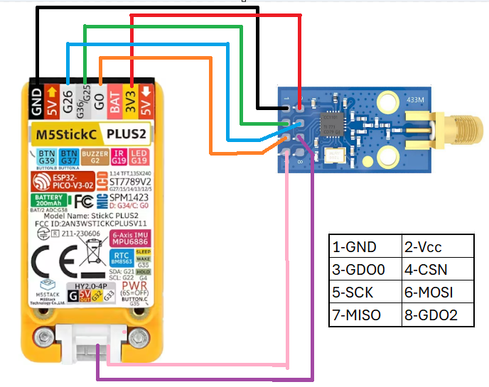
Connect the 4 wires on the back of g21 and g25, and modify the program code pin code
-
RE: M5Unit_CO2_Core2 example compilation error
@GordonD said in M5Unit_CO2_Core2 example compilation error:
fatal error: bsec2.h: No such file or directory
-
RE: Cannot compile M5Paper Weather sketch
weather information from openweathermap https://openweathermap.org on the e-ink display of the M5Paper. Please edit the config.h file with your own data. You need an api key from openweathermap.
Config.h#pragma once #define VERSION "Version 1.0" #define CITY_NAME "City" // change to your location #define LATITUDE 47.69732 #define LONGITUDE 8.63493 #define OPENWEATHER_SRV "api.openweathermap.org" #define OPENWEATHER_PORT 80 #define OPENWEATHER_API "your openweathermap api key" #define WIFI_SSID "your wifi ssid" #define WIFI_PW "your wifi password"onecall is not free anymore with new accounts.
https://github.com/Bastelschlumpf/M5PaperWeather/issues/9 -
RE: CoreMP135 Debian image
A command prompt starting with "$" indicates that the current user is in the normal user state, while a command prompt starting with "#" indicates that the user is in the super user (root) state.
The administrator account with the highest authority in the Linux system is root, also known as the superuser account. There are no restrictions on the use of this account. Administrators can make various changes to the system as long as they obtain this account, such as formatting and Mount the hard drive, add or delete user accounts, change various system services, update the system, etc.
How did you get into the terminal?
-
RE: CoreMP135 Debian image
https://docs.m5stack.com/en/core/M5CoreMP135
1.Watch the final instructional film(development framework)
2.use putty login as root -
RE: M5StickT2 bin file or board definition
Arduino IDE board as M5StickC (look at M5StickT.h)
https://github.com/m5stack/M5-StickT/archive/refs/heads/master.zipM5StickT_Lepton_opensource_v1.ino
#include <M5StickT.h>
#include <Wire.h>
#include <SPI.h>
#include "Lepton.h"
#include "img_table.h"
#include "esp_attr.h"
#include "esp_timer.h"
#include "img/ColorT.h"
used EasyLoader tools be easy
https://docs.m5stack.com/en/core/m5stickt -
RE: M5Tough, MQTT and Home Assistant
https://github.com/SmartHome-yourself/m5-tough-touchmenu-for-esphome?tab=readme-ov-file
Source link
https://github.com/esphome/feature-requests/issues/2166For information reference
install esphome
https://hackmd.io/@LHB-0222/ESPHOME_ESP32_SHTC3
board data
https://devices.esphome.io/devices/M5Stack-Fire
MQTT
https://koen.vervloesem.eu/blog/create-a-dashboard-for-your-mqtt-based-home-automation-system-with-the-m5stack-core-and-homepoint/ -
RE: M5StickC Plus2 not booting
I’m not sure if the situation is the same? The following is for reference
https://lab.sasapea.mydns.jp/2019/07/11/m5stickc-start-adapter/ -
RE: Timer Camera X with RTC
I2C is a one-master, multiple-slave approach. That is, one master device can connect to multiple slave devices and select and read through different device addresses. Please refer to the i2c protocol for details.
https://learn.adafruit.com/scanning-i2c-addresses/arduinohttps://github.com/m5stack/TimerCam-arduino/tree/master/examples/wakeup