Thanks you so much for your reply !
So, right now I'm understanding that I will have half IO than expected...
Thanks again, It helps me a lot
See you
Thanks you so much for your reply !
So, right now I'm understanding that I will have half IO than expected...
Thanks again, It helps me a lot
See you
Hello everybody !
I've ordered M5Stack Basic kit and I'm preparing my project.
I'm not able to find any schematic / picture that describes the link between MBus to IO of the Bottom module
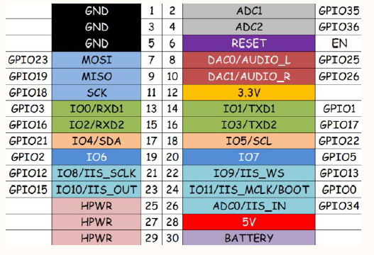
Following Schematic:
MBus have 30 pins with 20 GPIO
Following Bottom module picture:
Bottom module come with 46 pins with 30 IO...
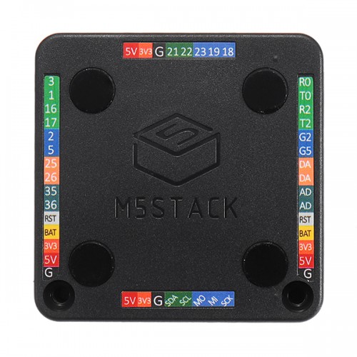
I can figure out connection for 5V, 3V3, GND, RST, BAT but for the other ???
2 pins are named "DA". What does it mean ?
"R0"/"T0": RX/TX from UART 1 ?
"R2"/"T2": RX/TX from UART 2 ?
"2" means GPIO2 ? So what "G2" means ?
Anyone can help ? Do you have a document regarding that ?
Many thanks for your help,
Max