M5Stack 2 Channel Oscilloscope
-
@calin
very nicely done! thanks for sharing sources to learn from -
Very nice. The speaker noise issue forced me to work out a fix to shut up the speaker on demand, without having to recompile every time. Here's how: you add an
end()method in Speaker.cpp:void SPEAKER::end() { ledcDetachPin(SPEAKER_PIN); }(declared in Speaker.h)
class SPEAKER {
  public:
    SPEAKER(void);
    void begin();
    void end();
Now you can call
M5.Speaker.end();any time to make sure the speaker shuts up. Works with any project – making it a generic solution. -
I fixed the speaker noise issue much much easyer.
Please check the updated version on: https://github.com/botofancalin/M5Stack-ESP32-OscilloscopeBTW!!!
The project is compiled on Visual Studio using the awsome vMicro plugin : http://www.visualmicro.com/ -
The DSO112A generates signal that's ok clean.
This M5Stack oscillo graphs something far noisier.
Why is that? Can this be fixed without lowering the sampling rate by smoothing the analog signal?EDIT: I connected to the wrong wires and didn't ground. Once grounded, disconnected USB and pinned to 35, the signal is very clean. Weird that I'd get a squarish signal when connected to AD

-
The maximum voltage on ESP32 ADC can read is 3.3v
The ESP32 don't have the voltage divider on ADC in as the DSO oscilloscope have.
Noises can cause high voltage levels, especially near computers, where you have lots of radio waves on different frequency. So even touching the input pin (35) with your hand, the voltage at the input pin can cause more than 3.3v, especially if the ESP is connected to PC by USB cable.Some basic filters and voltage dividers at the input pin, can solve that problem.
-
@calin and the ESP32 can be damaged by spiked above 3.3V, I read. How do I know if I damaged mine?
I'll add voltage divider, is there a way to remove spikes without killing the sensitivity? I am doing an FFT on the signal and don't want to smooth things out too much. -
If the DAC input was damaged, it won't pick up any signal that you feed to it...
-
Btw... check out the new development: http://forum.m5stack.com/topic/165/m5stack-multiapp-firmware
-
If I understand this correctly, the ESP32 analog input captures only positive voltage.
How do I get the full -/+ range in there? -
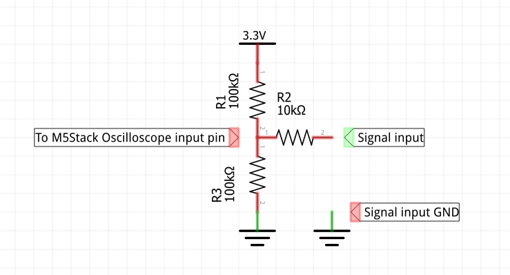
Make a voltage divider with 2 resistors (100k or so...) with one end connected to GND and the other end to 3.3v.
The middle of the divider connected to oscilloscope input pin.
Apply input signal to input pin and you get +/- 1.65v input range.
I designed the code to be used with this divider, that's why, without the divider, the oscilloscope line is at the bottom of the screen.
Once you connect the divider, the signal line will be at the middle of the screen just like on a normal oscilloscope. -
Without the voltage divider, the amplitude is the same, just offset by 1.65v?
-
The max amplitude is 3.3v. With the divider, the amplitude will be -1.65v to +1.65v (total 3.3v) The aplitude can be solved easy with a series of resistors at the imput. To change the input aplitude, replace the 10K resistor on the example below:
-
@calin 在 M5Stack 2 Channel Oscilloscope 中说:
he amplitude will be -0.65v to +0.65v (total 3.3v)
@calin, I think you meant the input signal range will be -1.65v to +1.65v (total 3.3v). :)
-
@pkourany 在 M5Stack 2 Channel Oscilloscope 中说:
@calin 在 M5Stack 2 Channel Oscilloscope 中说:
he amplitude will be -0.65v to +0.65v (total 3.3v)
@calin, I think you meant the input signal range will be -1.65v to +1.65v (total 3.3v). :)
yes. sorry for typo... edited now :)
-
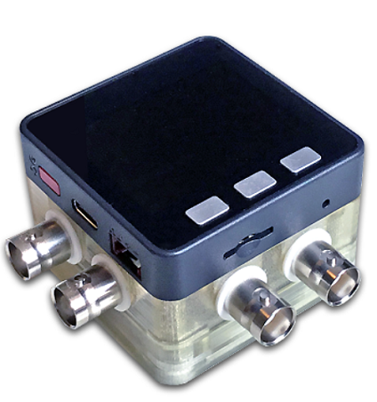
Awesome oscilloscope case - designed by Macsbug - infos here
-
This post is deleted! -
Its restarting every 5 seconds making it useless.. what can be my problem?
-
@chriswr Ok solved.. disable the watchdog..
disableCore0WDT();
disableCore1WDT();
Hello! It looks like you're interested in this conversation, but you don't have an account yet.
Getting fed up of having to scroll through the same posts each visit? When you register for an account, you'll always come back to exactly where you were before, and choose to be notified of new replies (either via email, or push notification). You'll also be able to save bookmarks and upvote posts to show your appreciation to other community members.
With your input, this post could be even better 💗
Register Login