@Gilbert
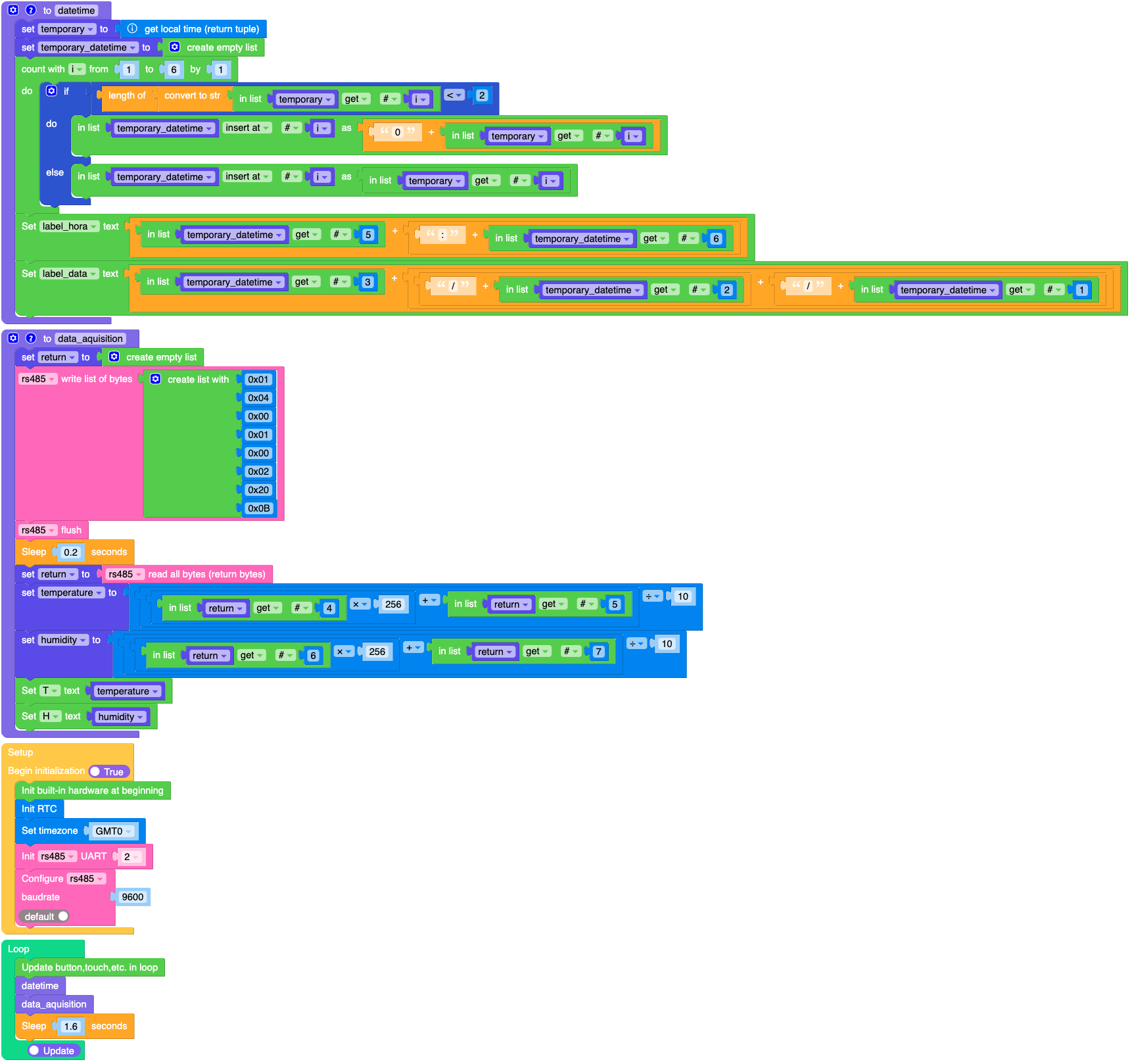
I have a routine for date and time in UIFlow2, see:
There is a part (if/do/else) where I add the "0" when the value has only 1 whole digit, for example: 5:5 for 05:05.
cheers!
@Gilbert
I have a routine for date and time in UIFlow2, see:
There is a part (if/do/else) where I add the "0" when the value has only 1 whole digit, for example: 5:5 for 05:05.
cheers!
I'm using UIFlow2 on Microsoft Edge and when I try to create a variable with the name of an object that already exists, I get the conflict information and even if I correct it, when I exit the variable creation window, UIFlow2 crashes and I have to reload the page to continue.
I have a simple code that displays the date, time, temperature and humidity data acquired by an RS485 device (XY-MD04), but the console keeps displaying the following messages:
E (18258813) mqtt_client: esp_mqtt_client_init(800): Memory exhausted
E (18258814) mqtt_client: Client was not initialized
E (18258815) mqtt_client: Client was not initialized
I have a CORE, 2x 2RELAY modules, an M5GO module (Port C), an RS485 converter via Port C and an XY-MD04 humidity and temperature sensor via RS485.
I'm not even using MQTT...
How do I know the size of my CORE's memory?
What is the size of the code I can use, and how do I know it?
My project is based on activating the relays based on RS485 data readings and timing (RTC). With the same code, sometimes it works, sometimes it presents execution errors.
I am very, very grateful for any help!
I noticed that if I turn Tough off and on again, the initial coordinates are -1 and 1, but if I just load a new version of the code, the last coordinates remain...
How could I clear the coordinates at the beginning of the code?
I also couldn't use the following block:
Thanks for any help!
I'm trying to read touches on the Tough screen, but when I start the code, it already comes with values of X (52) and Y (154) as if there was a touch.
By chance, it's exactly in the area where I expect it to be touched...
When I read the data in:
I get the following response: (52.0, 0.0, 154.0, 0.0)
I'm trying to read the touch like this:
Thank You!
@Robertof ab @felmue, thank you very much!
Now everything works!
I finally understood what was going on... I did some tests and then I managed to put an address in one module, then in the other and then I can access both at the same time. One of them was at 0x32 and the other at 0x33. I need 4 relays for my project... now the conditions acquired by a BME688 will change the states of the relays.
You helped a lot, not only to solve my problem but also to understand the process.
Success and health to you all!
Hi @felmue,
With one 2RELAY module, the result is: [52, 56, 64, 81, 102] and without is [52, 56, 64, 81]...
Sorry, I'm just starting with this...
Thank you very much...
Hi @Robertof,
I reproduced and understood your code, but as you can see in the images, nothing happens.
I'm also using UiFlow 1.13.6, it seems that there is some error in the module library...
I'm testing with only one 2RELAY module at a time, but both have the same problem.
I think the connection is fine... if I put the battery module underneath, the Core2 works without the USC-C connection, that is, with the attached battery (M5GO2 module).
Could there be an update in the Core2 firmware?
Thank you very much for your help!
Hi @Robertof,
Did you use UIFlow1?
I didn't find the 2RELAY module in UIFlow2.
I'll try to reproduce your tip and see if it works.
Thanks!
Hi Felix,
I removed the original battery and the gray part, bought the M5GO2 to replace it, but now I'm not even using it.
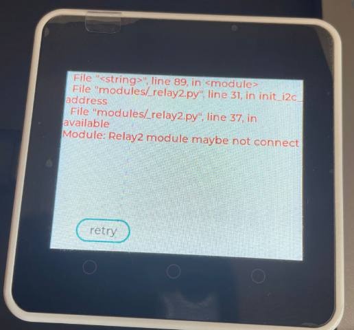
I'm trying with just one module, but when I use the examples (I tried with my code and it didn't work either), I get the message that the module is not attached... I tried with each of them individually.
Thank you.
I'm trying to use 2x 2RELAY modules on a Core2, is this possible?
I've tried everything, but I can't access the modules. I've tried with just one of them, via Arduino and via UIFLow, which says that the module is probably not attached.
I saw that it's possible to change the I2C address of the modules, but how do I do this, one at a time?
Thanks for any help...