Navigation

    M5Stack Community

    • Register
    • Login
    • Search
    • Categories
    • Recent
    • Tags
    • Popular
    • Users
    • Groups
    • Search
    1. Home
    2. Rop
    3. Best
    • Continue chat with Rop
    • Start new chat with Rop
    • Flag Profile
    • Profile
    • Following
    • Followers
    • Blocks
    • Topics
    • Posts
    • Best
    • Groups

    Best posts made by Rop

    • M5ez, a complete interface builder system for the M5Stack as an Arduino library. Extremely easy to use.

      Three weeks ago I was frustrated that it wasn't easier to build applications for the M5Stack. Today I release M5ez (pronounced "M5 easy") so that everyone can build things that look cool and just work.

      There are little things I want to make better still. It's not "done" - such things are never done - but you have to release at some point. But is good enough to build things on.

      A video can say more than a thousand words: please watch the video and have a look at the Github repository.

      https://github.com/ropg/M5ez

      As you will see I put some effort into documenting everything it does on Github. I hope you all will play with this and tell me what you like and don't like. I will continue to work on it and let you know in this thread when things are changing.


      ( A big thank you to Calin for some of the ideas. )

      posted in PROJECTS
      Rop
    • HOWTO: M5Stack with GPS, GSM and LoRa, all at the same time

      I have gotten all three radio boards to work with the M5Stack at the same time. This was a little more involved than it needs to be because documentation is either missing, not all in the same place or (in one case) apparently wrong. I'll use this post to document what I did and I have added a sketch that tests for complete functionality of the boards. I'll also add whatever else I know about the boards, including links to the datasheets of the used modules.

      In the process of doing this I figured out which pins to use to talk to which boards. In the black boxes with each board are lists of the pins used for each board (sometimes selectable with solder bridges, sometimes hardwired). In brackets are the available pins for that function via solder bridges on the board. Note that either the first or the only option for each pin has a little (sometimes invisible) trace shorting out the solder bridge, so the first option is already connected as you get the board. If you want to disconnect it, you'll have to break that trace by carefully scratching the circuit in-between the two pads of that solder bridge. In case you are low on GPIOs, the text below also lists which wires can be left unconnected for each board.


      LoRa

      MOSI	23
      MISO	19
      SCK	18
      CS	 5	(5 )
      RST	26	(26)
      INT	36	(36)
      

      0_1529773624099_LoRa2.jpg

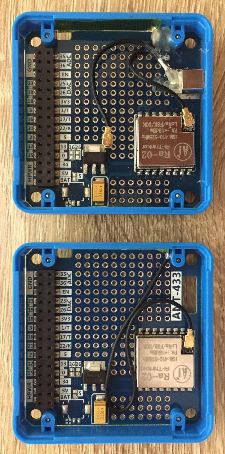
      In the case of the LoRa module, I'm using all the default pins, so there's no need to solder any bridges or scrape any wires. I bought a LoRa board and only then realised that LoRa is more fun if you have two boards (I had two M5Stack main units already). So I bought another one and got a slightly different unit. The picture shows the unit I first got on the bottom, and the second one on top. As you can see the new unit has a connector for an external antenna as well as an internal one. In the picture you see the pigtail for the internal antenna connected, it came with the external antenna jack connected. After taking this picture I taped down the other pigtail with a little square of duck tape so it doesn't touch anything important.

      The M5Stack LoRa uses the RA-02 radio module by AI-Thinker (datasheet) that is itself built around the Semtech SX-1278 transceiver chip (datasheet). If you actually start playing with the LoRa module, you might also want to read this article that GoJimmyPi wrote on it.

      Also note for your information that the following information is in the M5Stack documentation on the website as of Jun 20, 2018:

      0_1529522166892_LoRa2.png

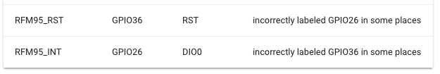
      This seems to be correcting something that is wrong elsewhere but it is actually wrong itself: RST is GPIO 26 and INT is 36. I measured it on both my boards with a multimeter, RST is really pin 26 and it would have to be because on the ESP32, GPIO 36 is input only so it could never drive the RST pin.

      People that want to save on available GPIO pins could leave off the reset pin. In that case, just pass -1 as the reset pin number, the second argument of LoRa.setPins in the M5LoRa library. If a pin is provided, all the library does is pull it low briefly once when you call LoRa.begin().

      It doesn't seem to affect all units, but in order to prevent a problem where the screen stays white, pull up pin 5, the CS pin of the LoRa, before initialising the m5 library. This is done as follows:

      pinMode(5,OUTPUT);
      digitalWrite(5,HIGH);
      m5.begin():
      

      GSM (SIM800L)

      TXD	16	(16)
      RXD	17	(17)
      RST	 2 (!)	(5)
      

      0_1529523088419_GSM.jpg

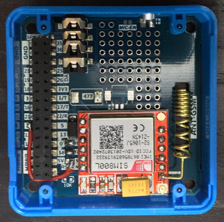
      Rx and Tx can use the default pins for UART2, but as you can see in the LoRa section above, we have already used the pin used to reset the GSM (GPIO5) as the LoRa ChipSelect pin, so we have to choose something else here. Unfortunately the solder jumpers do not allow for any other choice, so I carefully scratched out the hidden trace between the two pads of the 5 solder bridge and soldered in a little wire from the GSM side of that bridge across to a free pin, choosing GPIO2. Note that you want to unscrew the boards from the plastic frames with a little hex screwdriver before soldering wires in.

      The M5Stack SIM800L GSM board has a SIMCom "Core Board" module on it (the board with the red solder mask) that itself sports a SIM holder and a SIMCom SIM800L module (datasheet). This is a quad band GSM with GPRS, but no EDGE, 3G, LTE or anything else fancy.

      People that want to save on available GPIO pins could again leave off the reset pin: unless your code pulls it low it is not used.


      GPS

      TXD	13	(16, 3, 13)
      RXD	15 (!)	(17, 1, 5)
      PPS	34	(34, 35, 36)
      

      0_1529523186914_GPS.jpg

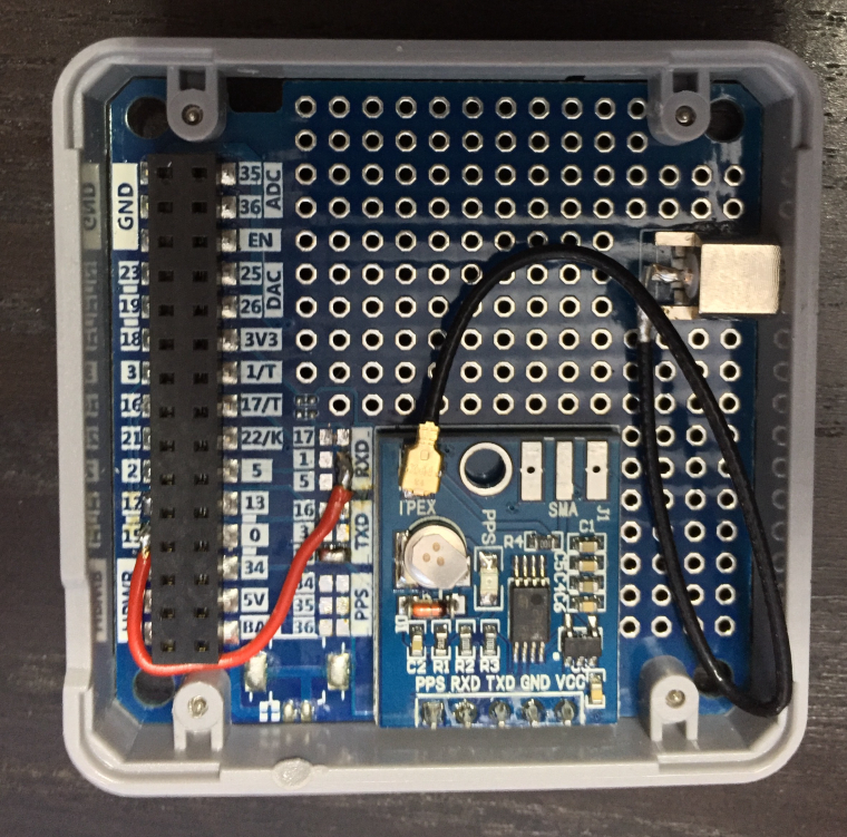
      The PPS signal provides one pulse per second, not very interesting unless you want to do very precise timing. I've already used the 17/16 default for the GSM above. So that means I started by carefully scraping away the traces between the solder bridges marked 16 and 17, checking with a multimeter that the connections are really gone. (Note that if you don't scrape away the traces inside the solder bridges, you will connect UART2 and UART1, leading to all sorts of surprisingly hard to debug grief.)

      I put the Tx at 13, which is a simple solder bridge, but the only solder bridge choices for Rx are 17 (UART2 default, in use by the GSM above), 1 (in use by the USB serial that talks to your computer) and 5 which is the default ChipSelect pin for the LoRa. So I put in a wire again, this time to GPIO15.

      The GPS module used is a u-blox NEO-M8 (datasheet).

      People that want to save on available GPIO pins could again leave off the reset pin, as well as the RX pin of the GPS module. After all: if you are happy with the NMEA data that the module provides by default, you don't need to talk to it. And you can also very safely leave off the PPS pin, if your code is not using this one pulse per second signal.
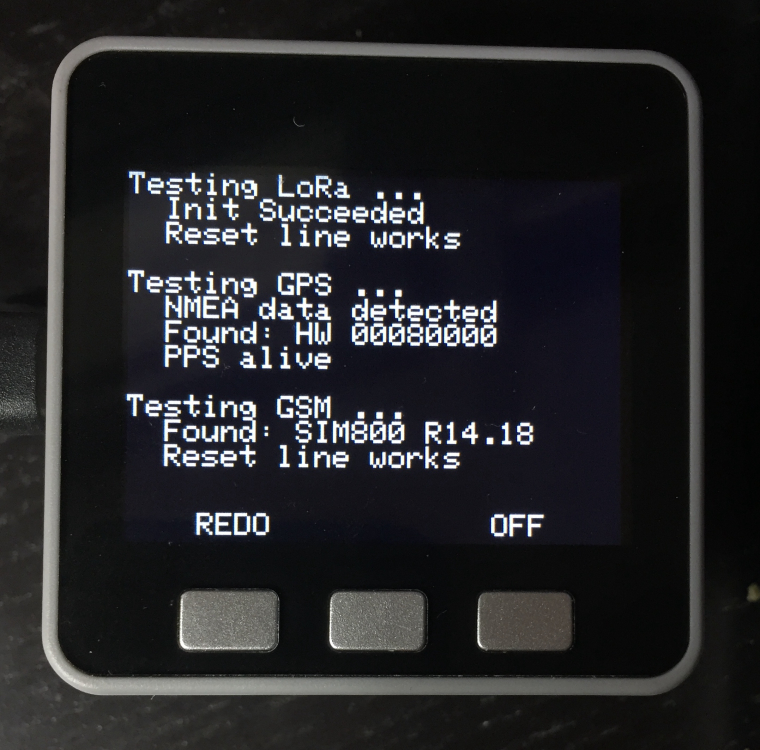

      Testing it all

      Now comes the time to test if all connections to each of the modules work. I have written BoardTest.ino, which should show you (in actually readable type) if your hardware is detected. You can set any pins you haven't hooked up to -1, the test program will then skip all the non-applicable tests.

      #include <M5Stack.h>
      #include <M5LoRa.h>
      
      HardwareSerial GPS(1);
      HardwareSerial GSM(2);
      
      // Change these if your boards are wired differently
      //
      // Any pins not hooked up can be set to -1 to skip tests
      //
      const int LORA_CS  =  5;
      const int LORA_RES = 26;
      const int LORA_INT = 36;
      const int GPS_RX   = 15;
      const int GPS_TX   = 13;
      const int GPS_PPS  = 34;
      const int GSM_RX   = 17;
      const int GSM_TX   = 16;
      const int GSM_RES  =  2;
      
      // The bytes to be sent to the GPS to request the version info packet back.
      const uint8_t UBX_MON_VER[] PROGMEM = { 0xb5, 0x62, 0x0a, 0x04, 0x00, 0x00, 0x0e, 0x34 };
      
      
      void setup() {
      
        String response;
        unsigned long started, last_ati, last_time, time_before_last;
        char resp_buf[50];
        unsigned int i, pps_state;
      
        if (LORA_CS != -1) {
          pinMode(LORA_CS, OUTPUT);
          digitalWrite(LORA_CS, HIGH);
        }
        m5.begin():
      
        M5.Lcd.setTextSize(2);
      
        // Test LoRa
        ConsoleOutput ("Testing LoRa ...");
        if (LORA_CS != -1 && LORA_INT != -1) {
      	LoRa.setPins(LORA_CS, LORA_RES, LORA_INT);
      	if (LoRa.begin(433E6)) {
      	  ConsoleOutput("  Init Succeeded");
      	  if (LORA_RES != -1) {
      		LoRa.setPins(LORA_CS, -1, LORA_INT);
      		pinMode(LORA_RES, OUTPUT);
      		digitalWrite(LORA_RES, LOW);
      		if (LoRa.begin(433E6)) {
      		  ConsoleOutput("  Reset line does not work");
      		} else {
      		  ConsoleOutput("  Reset line works");
      		}
      		digitalWrite(LORA_RES, HIGH);
      	  } else {
      		ConsoleOutput ("  Skipping reset test");
      	  }
      	} else {
      	  ConsoleOutput("  Hardware Not Found");
      	}
        } else {
      	ConsoleOutput("  Skipping test");
        }
      
        ConsoleOutput("");
      
        // Test GPS
        ConsoleOutput ("Testing GPS ...");
        if (GPS_TX != -1 ) {
      	GPS.begin(9600, SERIAL_8N1, GPS_TX, GPS_RX);
      	GPS.setTimeout(1000);
      	started = millis();
      	while (true) {
      	  response = GPS.readStringUntil(13);
      	  response.replace("\n", "");
      	  if (response.substring(0,2) == "$G") {
      		ConsoleOutput("  NMEA data detected"); 
      		if (GPS_RX != -1) {
      		  GPS.setTimeout(500);
      		  GPS.flush();
      		  GPS.write(UBX_MON_VER, sizeof(UBX_MON_VER));
      		  GPS.readStringUntil(0xb5);
      		  GPS.readBytes(resp_buf, 50);
      		  if (resp_buf[0] == 'b') {
      			response = "";
      			for (i = 35; i < 44 ; i++) response = response + resp_buf[i];
      			ConsoleOutput("  Found: HW " + String(response));
      		  } else {
      			ConsoleOutput("  No response. RX ok?");
      		  }
      		} else {
      		  ConsoleOutput("  Skipping bidir test");
      		}
      		break;
      	  }
      	  if (millis() - started > 2000) {
      		ConsoleOutput("  No NMEA data found");
      		break;
      	  }
      	}
      	GPS.end();
        } else {
      	ConsoleOutput("  Skipping serial tests");
        }
      
        if (GPS_PPS != -1) {
      	pinMode(GPS_PPS, INPUT);
      	pps_state = digitalRead(GPS_PPS);
      	started = millis();
      	while (true) {
      	  if (digitalRead(GPS_PPS) != pps_state) {
      		if (millis() - time_before_last > 900 && millis() - time_before_last < 1100) {
      		  ConsoleOutput("  PPS alive");
      		  break;
      		}
      		pps_state = digitalRead(GPS_PPS);
      		time_before_last = last_time;
      		last_time = millis();
      	  }
      	  if (millis() - started > 3000) {
      		ConsoleOutput("  PPS not detected");
      		break;
      	  }
      	}
        } else {
      	ConsoleOutput("  Skipping PPS test");
        }
      
        ConsoleOutput("");
      
        // GSM testing
        ConsoleOutput("Testing GSM ...");
        if (GSM_TX != -1 && GSM_RX != -1) {
      	if (GSM_RES != -1) {
      	  pinMode(GSM_RES, OUTPUT);
      	  digitalWrite(GSM_RES, HIGH);
      	}
      	GSM.begin(9600, SERIAL_8N1, GSM_TX, GSM_RX);
      	GSM.setTimeout(200);
      	GSM.println("ATI");
      	started = millis();
      	last_ati = millis();
      	while (true) {
      	  // send "ATI" every second in case the modem just woke up
      	  if (int(last_ati / 1000) < int(millis() / 1000)) {
      		GSM.println("ATI");
      		last_ati = millis();
      	  }
      	  response = GSM.readStringUntil(13);
      	  response.replace("\n", "");
      	  if (response.length() > 6) {
      		ConsoleOutput("  Found: " + String(response));
      		if (GSM_RES != -1) {
      		  started = millis();
      		  GSM.println("ATI");
      		  digitalWrite(GSM_RES, LOW);
      		  while (true) {
      			response = GSM.readStringUntil(13);
      			response.replace("\n", "");
      			if (response.length() > 6) {
      			  ConsoleOutput("  Reset line broken");
      			  break;
      			}
      			if (millis() - started > 2000) {
      			  ConsoleOutput("  Reset line works");
      			  break;
      			}
      		  }
      		  digitalWrite(GSM_RES, HIGH);
      		} else {
      		  ConsoleOutput("  Skipping reset test");
      		}
      		break;
      	  }
      	  if (millis() - started > 4000) {
      		ConsoleOutput("  No response to ATI");
      		break;
      	  }
      	}
      	GSM.end();
        } else {
      	ConsoleOutput("  Skipping tests");
        }
      
        M5.Lcd.setCursor(45,220);
        M5.Lcd.print("REDO");
        M5.Lcd.setCursor(235,220);
        M5.Lcd.print("OFF");
      
      
      }
      
      void loop() {
      
         M5.update();
      
        if (M5.BtnC.wasPressed()) {
      	M5.setWakeupButton(BUTTON_C_PIN);
      	M5.powerOFF();
        }
      
        if (M5.BtnA.wasPressed()) {
      	M5.Lcd.clear();
      	M5.Lcd.setCursor(0,0);
      	setup();
        }


      }
      
      void ConsoleOutput(String message) {
        Serial.println(message);
        M5.Lcd.println(message);
      }
      

      Et voila:

      0_1530214217512_it-all-works.jpg

      posted in Lessons and Guides
      Rop
    • M5Button & M5Touch: progress update

      I just issued a Pull Request to pull the advances in M5Button and M5Touch into the M5Core2 library. As everything seems stable and nothing breaks anything existing, I hope m5Stack not only takes them on board but also releases a new version of the Arduino library so more people get to use the new features.

      I have also filed a PR on the M5Stack library for the 3-button 'Core-ESP32' and 'Fire' devices. It (naturally) does not have M5Touch but offers all of M5Button's button-drawing goodness and events as well as the same neat tweaks on the M5Display object. All the files are identical, with any changes behind #ifdef statements, so there's no need to have multiple versions of anything. i also hope M5Stack takes these on as soon as possible and also releases a new version.

      posted in Core 2
      Rop
    • HOWTO: M5Stack Fire - use the full 16MB with the Arduino IDE (UPDATED)

      For reasons unclear to me, the M5Stack Fire support added to the Board Manager does not change the size of the flash from the original M5Stack Core. What that means is that you cannot use all that extra flash (Fire has 16 MB, classic M5Stack has 4 MB).

      Here's how to use the extra space:

      Find the directory that on my Mac is at

      ~/Library/Arduino15/packages/esp32/hardware/esp32/1.0.0/tools/partitions

      (It's probably named slightly different on Windows machines, don't use those.)

      There, add a file called default_16MB.csv and put the following lines in it:

      # Name,   Type, SubType, Offset,  Size, Flags
      nvs,      data, nvs,     0x9000,  0x5000,
      otadata,  data, ota,     0xe000,  0x2000,
      app0,     app,  ota_0,   0x10000, 0x640000,
      app1,     app,  ota_1,   0x650000,0x640000,
      eeprom,   data, 0x99,    0xc90000,0x1000,
      spiffs,   data, spiffs,  0xc91000,0x36F000,
      

      and add another file called large_spiffs_16MB.csv and put in it:

      # Name,   Type, SubType, Offset,  Size, Flags
      nvs,      data, nvs,     0x9000,  0x5000,
      otadata,  data, ota,     0xe000,  0x2000,
      app0,     app,  ota_0,   0x10000, 0x480000,
      app1,     app,  ota_1,   0x490000,0x480000,
      eeprom,   data, 0x99,    0x910000,0x1000,
      spiffs,   data, spiffs,  0x911000,0x6EF000,
      

      Now go two directories up (so for me that would be ~/Library/Arduino15/packages/esp32/hardware/esp32/1.0.0) and edit the file boards.txt.

      search for m5-stack-fire.upload.maximum_size and replace that line with:

      m5stack-fire.upload.maximum_size=6553600
      

      Then replace the (next) line (m5stack-fire.upload.maximum_data_size) with:

      m5stack-fire.upload.maximum_data_size=4521984
      

      Then find m5stack-fire.build.partitions and replace that line with:

      m5stack-fire.build.partitions=default_16MB
      

      Then insert the following new section between the PSRAM and UploadSpeed sections:

      m5stack-fire.menu.PartitionScheme.default=Default (2 x 6.5 MB app, 3.6 MB SPIFFS)
      m5stack-fire.menu.PartitionScheme.default.build.partitions=default_16MB
      m5stack-fire.menu.PartitionScheme.large_spiffs=Large SPIFFS (7 MB)
      m5stack-fire.menu.PartitionScheme.large_spiffs.build.partitions=large_spiffs_16MB
      m5stack-fire.menu.PartitionScheme.large_spiffs.upload.maximum_size=4685824
      

      And then restart the IDE and you can use the full flash: I chose 2 x 6.5 MB OTA partitions, 3.6 MB SPIFFS. So now the M5ez demo program uses only 18% of one OTA partition. Or opt for a SPIFFS partition that will hold a whopping 7 MB. Nice...


      I have filed a pull request at https://github.com/espressif/arduino-esp32 with these changes.


      M5Stack people: I know you don't answer questions or talk to us in general, but this is something you people should be doing, not some dude in the community...

      posted in Lessons and Guides
      Rop
    • M5Core2 library fork that supports multi-touch and provides Arduino-style virtual buttons [update: and gestures and events] [update2: MERGED !]

      If you use this fork of the M5Core2 library, you get a Touch object that not only supports the existing API but also a newer API that reads up to two simultaneous touches from the touch sensor. (Limitations apply, see below.)

      The three touch circles are available as BtnA - BtnC and you get a TouchButton object class that lets you create additional Arduino-style buttons for any rectangle on the screen, and then you can use the regular Arduino functions like isPressed() etc. You can also define handler functions for the pressed and released events for any given TouchButton. You can see everything demonstrated if you run the example sketch from the library examples (also copied below).

      It's a drop-in replacement: the old touch API still works and the M5Stack factory test compiles fine. I have filed a Pull request on GitHub, so hopefully this all goes into the next version of the stock library.


      Touch object documentation (from src/touch.h)

      M5Stack Core2 touch library
      
      	Touch is provided by a FocalTech FT6336 chip, which supports two
      	simultaneous touches (see below for limitation).
      
      	This library is initialised in M5Core2.h. An instance "M5.Touch" exists
      	and can be used after you call "M5.begin()".
      
      
      Two-touch API
      
      	TouchPoint_t
      		Variable type to hold a touchpoint. Has members x and y that hold
      		the coordinates of a touch.
      
      	M5.update()
      		In the loop() part of your sketch, call "M5.update()". This is the
      		only part that talks to the touch interface. It updates the data
      		used by the rest of the two-touch API.
      
      	uint8_t M5.Touch.points
      		Contains the number of touches detected: 0, 1 or 2.
      
      	TouchPoint_t M5.Touch.point[0], M5.Touch.point[1]
      		M5.Touch.point[0] and M5.Touch.point[1] hold the detected touches.
      		
      	bool M5.Touch.inBox(x0, y0, x1, y1)
      		true if any valid touch is found in the supplied rectangle. Can be
      		used directly, but you'll be happier with the TouchButton library.
      
      	bool M5.Touch.hasChanged()
      		true if anything has moved on the touch screen since the last time
      		this function was called.
      
      
      Note about multi-touch
      
      	The M5Stack Core2 touch display is only multi-touch in one dimension.
      	What that means is that it can detect two separate touches only if they
      	occur on different vertical positions. This has to do with the way the
      	touch screen is wired, it's not something that can be changed in
      	software. So you will only ever see two points if they do not occur
      	side-by-side. Touches that do happen side-by-side blend into one touch
      	that is detected somewhere between the actual touches.
      
      	While this limits multi-touch somewhat, you can still create multiple
      	buttons and see two that are not on the same row simultaneously. You
      	could also use one of the buttons below the screen as a modifier for
      	something touched on the screen.
      
      
      Legacy single touch API
      
      	TouchPoint_t
      		Variable type to hold a touchpoint. Has members x and y that hold
      		the coordinates of a touch.
      
      	bool M5.Touch.ispressed()
      		true when the touch screen is pressed.
      
      	TouchPoint_t M5.Touch.getPressedPoint()
      		Returns the point that is being pressed, or (-1,-1) is nothing is
      		pressed. In case two points are pressed, this will return one of
      		them.
      
      	HotZone_t
      		Defines a zone on the screen, comes with built-in functions to test
      		if a given point is within that zone. Similar but more enhanced
      		functionality is provided by the TouchButton library, see below.


      TouchButton documentation (from src/utility/M5TouchButton.h)

      M5Stack Core2 M5TouchButton library version 1.0
      
      	Implements Arduino button library compatible buttons for any chosen
      	rectangle on the M5Stack Core2 touch screen. Up to two buttons can be
      	pressed simultaneously.
      
      
      Basic usage
      
      	For this to work, M5.update() has to be ran to scan for button presses,
      	so make sure to put that in the loop() part of your sketch.
      
      	To create a button, just create a button variable that defines the area
      	on the touch screen for the button. E.g.:
      
      		TouchButton testButton(0, 0, 50, 50);
      
      	The format is x0, y0, x1, y1 where x0, y0 is the left top of the button
      	and x1, y1 is the right bottom. From here on you can use all the
      	standard Arduino button functions such that testButtton.isPressed()
      	will now tell you if the top left of the screen is touched.
      
      	Buttons will be deleted from the list if their variables go out of
      	focus, so if you define buttons in a subroutine, they will not be in
      	your way anywhere else.
      
      	If button areas overlap, both buttons will become pressed if the
      	overlap is touched. Note that you cannot ever press two non-overlapping
      	buttons simultaneously because the M5Core2 touch screen is not
      	multi-touch.
      
      	The three buttons BtnA, BtnB and BtnC from the older M5Stack units come
      	already implemented as buttons that lie just below the screen where the
      	three circles are. If you want them to be a little bigger and also
      	cover the area of the screen where you may be showing labels for the
      	buttons, simply raise the top of the buttons like this:
      
      		 M5.BtnA.y0 = M5.BtnB.y0 = M5.BtnC.y0 = 220;
      
      	The screen is 320 x 240 pixels, the touch sensor is 320 x 280, 40
      	pixels are below the screen.
      	
      
      Note about multi-touch
      
      	The M5Stack Core2 touch display is only multi-touch in one dimension.
      	What that means is that it can detect two separate touches only if they
      	occur on different vertical positions. This has to do with the way the
      	touch screen is wired, it's not something that can be changed in
      	software. So you will only ever see two points if they do not occur
      	side-by-side. Touches that do happen side-by-side blend into one touch
      	that is detected somewhere between the actual touches.
      
      	While this limits multi-touch somewhat, you can still create multiple
      	buttons and see two that are not on the same row simultaneously.
      	
      
      Calling functions automatically
      
      	In addition to the coordinates, you can optionally specify a
      	function to be called when a button is pressed, a function for when
      	it's released, as well as an id number to figure out what button was
      	pressed if multiple buttons are handled by the same function.
      	
      	Naturally you can also have a separate function for each key in which
      	case you doon't need to supply an id number (it defaults to 0).
      	Function pointers and id can also be retrieved or set later, with
      	btn.fnPress, btn.fnRelease and fn.id. So to attach a function to the
      	leftmost button under the screen, simply say:
      	
      		M5.BtnA.fnPress = myFunction;


      Touch example (examples/Basics/Touch/touch.ino)

      #include <M5Core2.h>
      
      void setup() {
        M5.begin();
      }
      
      void loop() {
        M5.update();
        if (M5.Touch.hasChanged()) {
          if (!M5.Touch.points) Serial.print("--");
          if (M5.Touch.points) Serial.printf("x: %d, y: %d        ",  M5.Touch.point[0].x, M5.Touch.point[0].y);
          if (M5.Touch.points == 2) Serial.printf("x: %d, y: %d",  M5.Touch.point[1].x, M5.Touch.point[1].y);
          Serial.println();
        }
      }
      
      void btnHandler(TouchButton &btn) {
        M5.Lcd.fillRect(btn.x0, btn.y0, btn.x1 - btn.x0, btn.y1 - btn.y0, btn.isPressed() ? WHITE : BLACK);
      }
      
      TouchButton lt = TouchButton(0, 0, 159, 119, btnHandler, btnHandler);
      TouchButton lb = TouchButton(0, 120, 159, 240, btnHandler, btnHandler);
      TouchButton rt = TouchButton(160, 0, 320, 119, btnHandler, btnHandler);
      TouchButton rb = TouchButton(160, 120, 320, 240, btnHandler, btnHandler);
      
      posted in Core 2
      Rop
    • RE: Simple Touch Keyboard

      Tried my hand at a keyboard too... (Can't type on non-qwerty...)

      Found that the horizontal precision is actually nice on this touch sensor, it's the vertical registration where I go wrong the most. So I made a keyboard with only three rows of keys, and I can actually type on it. Trick for me is to briefly but consciously look at a key before hitting it: as soon as I start relying on muscle memory my error rate goes way up. Also find that if correcting mistakes is easy enough and doesn't lead to additional mistakes, it's OK to have some misses. Try the experimental branch on my repo, the Touch / Keyboard example for a taste.

      The help screen (which now just says "HELP"), will eventually explain that space is swipe right, backspace is swipe left and to get upper case, just drag a letter upwards. If you move across the typed text you move the caret unless text is wider than window, then you (smoothly..) drag the text. In that case drag down to bottom key row and then sideways to move caret. You can grab the text anywhere above the keys, even in the help/prompt bar.

      Note that I used sprites both for the text entry field and also (briefly) for the keyboard change so that I prevent flicker. Also, there's now M5.Buttons.pushState() and M5.Buttons.popState() to save and restore buttons, gestures and eventhandlers so that one can switch context (such as into and out of keyboard mode) without setting up one's entire environment again.

      Lots of emerging thoughts on how to structurally build out from here, but also just happily playing around building cool stuff and seeing how I would most like things to work for people to program with ease.

      posted in Core 2
      Rop
    • ESP-IDF and ESP-ADF on M5Core2

      Hi all,

      I've created some components that might be useful for those that like programming M5Core2 using Espressif's Integrated Development Framework (ESP-IDF). It's a bit more complex to wrap your head around than Arduino, but then compiling is blazingly fast and you end up with more powerful tools at your disposal. And with the components I built at least some of the pain out of getting something working on the M5Core2.

      • m5core2_esp-idf_demo is a demo program that uses the lvgl display/touch interface library and also showcases both my i2c_manager thread-safe library as well as the m5core2_axp192 library to set up and control the power management in the M5Core2.

      • m5core2_adf is a component that will let you use the M5Core2 as an audio board for Espressif's Audio Development Framework (ESP-ADF). Anything from playing and recording sound to streaming MP3s and even voice recognition.

      posted in PROJECTS
      Rop
    • Ideas, helping M5Stack document stuff...

      Dear people at M5Stack,

      First of all: thank you for making cool things....

      But ehm... why don't we start using (for instance) the wiki at your Github repository to document them a little more? I realise you have a bunch of really busy engineers making products and not all speaking english, but if you really have no time to document, please just dump code, schematics, PCB designs, 3D CAD or whatever else and we'll help making it look pretty and tell people how it works in ways that they can understand. This helps us build stuff and having stuff documented well makes more people buy more product. Win/win, right?

      The alternative is that we start reverse-engineering your made-for-prototyping hardware. Which is doable, but a silly waste of time. Where are you located, and what are your documents written in? And are there volunteers here on the forum that speak Mandarin/Cantonese?

      My personal off-the-top-of-my-head wishlist...

      • The schematics and any other documentation regarding the FACES keyboards and the plate underneath, so we can figure out if we can detect its presence and if/how we can trigger from software the reset-button double-click power off state that also turns off the keyboard. (If that is not triggerable from software, it probably should be in the next version.)

      • Any internal data you have on battery charging (capacities, time needed, USB power modes supported, etc etc) for all three batteries (the small bottom plate that comes with the unit, the battery stackable unit and the FACES bottom.

      • The thing with button A and wifi: which units does it affect, is the fix with the analogRead the best way, can one use speaker, button A and wifi at the same time without the squealing sound? Does it affect the newer units?

      But I am sure there is much more people can think about.

      This is, in my mind, the coolest tinkering hardware currently out there. I'd like to see it get critical mass and have a rapidly expanding ecosystem of stackable boards, software libraries etc, etc. This cannot all be done by a small group inside one company. You will have your own ideas of where you are taking this, and you have the benefit of seeing what actually sells in the market, but I think you would do even better if you also to talk to the rest of the world more.


      Somewhat unrelated, but now that I'm talking to you anyway: here's some random ideas from myself or others in this community:

      • The proto board and the other boards should have the pins on the other side of the connector accessible. ( maybe like http://forum.m5stack.com/topic/95/custom-prototype-board )

      • In future versions of the stackable boards, more pins need to be solder-jumper options: too many pin conflicts already.

      • Maybe sell a cheap OEM laserdiode barcode reader in a stackable module, looking out at the top of the screen, so with the FACES bottom it can be a handheld inventory device etc etc. (Or even a small camera, to be used as a camera or for QR and other 2D barcodes?)

      posted in PRODUCTS
      Rop
    • RE: M5ez 2.0: testers wanted...

      @ajb2k3 You're absolutely right: the feature to be able to change the captions of text menus while the menu is active had introduced this error on some image menu displays. Fixed in version 2.0.1 which I just released. :)

      posted in M5EZ
      Rop
    • RE: HOWTO: M5Stack Fire - use the full 16MB with the Arduino IDE (UPDATED)

      I updated the post (the SPIFFS was the original size while I had made space to make it bigger) and added a menu option for 7MB SPIFFS. Have also filed the pull request at espressif, all detailed in the edited lead post.

      posted in Lessons and Guides
      Rop
    • RE: M5ez, a complete interface builder system for the M5Stack as an Arduino library. Extremely easy to use.

      @yurikleb I haven't really played with micropython much: I built M5ez in part because micropython didn't really run well on the memory-restrained M5Stack I had. I know things ar edifferent with the Fire, and it wouldn't be crazy hard to create python bindings for M5ez. I just haven't done any python bindings before, and I'd prefer to stay focused on making M5ez better instead. But I will gladly support anyone else that feels like doing the python bindings.

      (I even had crazy thoughts of a Web-IDE where you can essentially build the entire interface in the browser, What You See Is What You Get. But seems a little ambitious and not sure how much actual use it would get.)

      posted in PROJECTS
      Rop
    • Backticks... (Request to admins)

      Hello people running this board...

      Can we please have a sticky post pointing out that people should put code between two lines with three backticks (These things: -> ` <-) on them so that when they post their code it ends up looking like this:

      #include <M5ez.h>
      
      void setup() {
          ez.begin();
      }
      
      void loop() {
          ez.msgBox("M5ez minimal program", "Hello World !", "Settings");
          ez.settings.menu();
      }
      

      and not like this:

      #include <M5ez.h>

      void setup() {
      ez.begin();
      }

      void loop() {
      ez.msgBox("M5ez minimal program", "Hello World !", "Settings");
      ez.settings.menu();
      }

      posted in Lessons and Guides
      Rop
    • LoRa module and FACES keyboard

      Just a quick heads up: the LoRa module, by default, uses GPIO5 as CS (Chip Select), and GPIO 5 is also the IRQ wire of the FACES keyboard, pulled low when data is ready to be gotten via I2C and high again when it sends the data. So cut the trace between the two solder-pads and put the CS of the LoRa somewhere else with a little wire. (The FACES keyboard does not seem to have a way that I see to move the IRQ.)

      See http://forum.m5stack.com/topic/239/howto-m5stack-with-gps-gsm-and-lora-all-at-the-same-time for details on the wires.

      People at M5Stack: the github README.md of your FACES repo says "FACES", that is it. It's nice (and has been helpful) to have the Arduino code for the processors on the 3 keyboard boards, but really it would be better still to have a schematic and some actual documentation.

      Also, the keyboard lives at I2C addess 0x88, but the I2C scanners I used does not find it there. Is there a way to detect the keyboard without waiting for the user to press a key?

      posted in PRODUCTS
      Rop
    • RE: M5ez, a complete interface builder system for the M5Stack as an Arduino library. Extremely easy to use.

      @macle Depends on what you need. Are you mass-programming a bunch of devices? The easiest way is probably to add a bit of code to your program that does this. Haven't tested, but something like this should work:

      void setup() {
        ez.begin();
        [...]
        if (ez.wifi.indexForSSID("your-ssid") == -1) {
          ez.wifi.add("your-ssid", "your-key");
          ez.wifi.writeFlash();
        }
        [...]
      }
      

      (It's all here in the manual.)

      posted in PROJECTS
      Rop
    • M5ez 2.1.0 released

      Hi all,

      Sorry to have been away from this for a bit... I just released M5ez version 2.1.0, with the following fixes:

      • Canvas scrolling off by default
      • Fixed off by one in wifi network handling (#32)
      • Added ez.clock.waitForSync()
      • Move wire.begin so it doesn't get run when FACES is off

      Note that if your code uses scrolling on the canvas, you have to turn that on first using ez.canvas.scroll(true).

      posted in M5EZ
      Rop
    • RE: M5Core2 library fork that supports multi-touch and provides Arduino-style virtual buttons [update: and gestures and events] [update2: MERGED !]

      It got merged... Yay!

      posted in Core 2
      Rop
    • M5Sound 😎

      I just wrote a simple polyphonic background synthesizer library for the Core2:

      #include <M5Core2.h>
      
      Synth a;
      
      void setup() {
        M5.begin();
        a.freq = 1000;
        a.gain = 0.4;
      }
      
      void loop() {
        M5.update();
        if (M5.Buttons.event == E_TOUCH) a.start();
        if (M5.Buttons.event == E_RELEASE) a.stop();
      }
      

      You can have multiple Synth instances, their output is mixed. Every synth has attack, decay, sustain release envelope, and the waveform member can be set to SINE, SQUARE, SAWTOOTH, TRIANGLE or NOISE. Sound will continue as long as M5.update() is called. Default attack and release at 5 ms, so no ugly clicks.

      Under 200 lines in the cpp file...

      A few more convenience features coming, buffering to improve a bit still, but this is the core.

      Do play with the DTMF_dialer example, and try holding it sideways...

      It's all on the M5Sound branch of my fork.

      posted in Core 2
      Rop
    • RE: M5Sound 😎

      @vkichline Made checkRotation more generic:

      bool checkRotation(uint16_t msec) {
        if (millis() - rotationLastChecked < msec) return false;
        rotationLastChecked = millis();
        const float threshold = 0.85;
        float ax, ay, az;
        M5.IMU.getAccelData(&ax, &ay, &az);
        uint8_t newRotation;
        if      (ay >  threshold) newRotation = 1;
        else if (ay < -threshold) newRotation = 3;
        else if (ax >  threshold) newRotation = 2;
        else if (ax < -threshold) newRotation = 0;
        else return false;
        if (M5.Lcd.rotation == newRotation) return false;
        columns = newRotation % 2 ? 4 : 3;
        M5.Lcd.clearDisplay();
        M5.Lcd.setRotation(newRotation);
        return true;
      }
      

      All it needs is a global uint32_t rotationLastChecked and for you to have ran M5.IMU.Init() (which seems to set power things on the MPU, so there's probably a reason it's not in M5.begin(), haven't read the datasheet.)

      checkRotation returns a bool and takes the number of milliseconds between checks. It returns true if it has already rotated and cleared the display for you and needs you to set things up again. So my loop() now does if (checkRotation(1000)) doButtons()

      posted in Core 2
      Rop
    • Windowing environment

      Hey...

      Wouldn't it be cool to have something like Qt for the Core2? A real windowing environment with widgets, etc etc?

      posted in Core 2
      Rop