@scroggyg The file exists, could the path length be too long?
C:\Users\xxxxxxxxxxxxxx\xxxxxxxxxxxxxx\Documents\Arduino\hardware\espressif\esp32\tools\sdk\esp32s3\include\esp_rom\include\esp32\rom
S
Offline
Posts
-
RE: esp32/rom/rtc.h No such file or directory
-
esp32/rom/rtc.h No such file or directory
I am trying to build the 6060_Push.ino in Arduino IDE 2.3.6.
I have added the additional boards

and

and the STamPLC libraries

Yet it can't find rtc.hWhat else do I need to load?
Thanks -
RE: Using 6060 Push
@scroggyg Neither the 6060 push or the STAMP PLC are provided with connectors. The connector type seems to be ht-3.96 4p which I can only find by importing from China. I have some PowerCAN modules which were supplied with this connector, could you please provide these connectors in future?
-
RE: Using 6060 Push
I see from the code the ID is stored in EEPROM, but I suspect there can only one device on the bus at a time when the address is set.
Also I suspect I would use an address other than 1, as this is the default address, set when a new device is added -
Using 6060 Push
Can I connect multiple 6060 push on the same RS485 bus. I see that we can set a device ID, is this stored on the device after a power cycle?
-
M5Tab Running out of memory error
I am writing an Python application for the M5 TAB5, which was running well but I am now getting memory errors
I am not using any networking in the application. before upgrading 2.3.6 Hotfix 2 it was fine
-
RE: TAB5 python Crash
@scroggyg I rewired the board to Port A and the code works. There seems to be an issue connecting an I2C device on the ExtPort2, the python crashes when the Extio2 is connected. That is all I have tested, there may be other issues.
-
RE: TAB5 python Crash
@scroggyg Felix, I ran your code, but changed to the internal I2C G31 & G32 the bus I am running the M0 from and it crashes.
I have made a board using the M0 from the EXtio2, I am using this successfully with other TAB5s -
RE: TAB5 python Crash
Thanks Felix, I updated the TAB5 to V2.3.6-hotfix2 but the problem remains. As a trest I write once a second and that works, when I then call it in another function it panics
This code panics
This code works
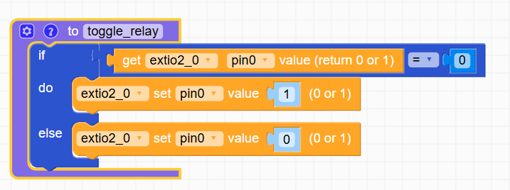
Any help would be appreciated -
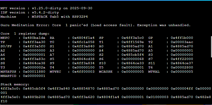
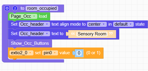
TAB5 python Crash
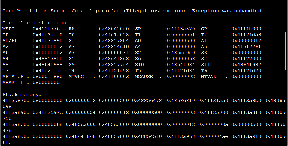
I was trying to write an output on EXTIo2 and I got a python crash and a dump.
I then tried to update the TAB5 to V2.3.6-hotfix2.
The device programmed and the default UIFlow screen is showing, but now I cannot program the device.
I reverted to 2.3.5 and I can program the TAB5 -
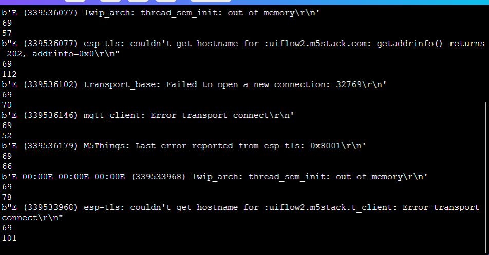
M5Tab fatal error
I am now working with M5UI, and I am getting a core panic. The message is. The device resets and then the application runs, but the terminal has disconnected and print to the terminal no longer works.
Surely I shouldn't be able to create a core panic using UIFlow2?
 -
TAB5 watchdog after firmware update
I have recently updated to the latest firmware.
I have a relatively simple program that uses a watchdog, and it is now reasonably impossible to reprogram it.
To recover I have to use M5Burner, and that takes several attempts.
It would seem that the watchdog is remaining active during the programming phase, causing the TAB5 to reset mid programming?
Has anyone else seen this? -
RE: Tab5 RS485 connector
I do think it is too fragile to be of any practical use, I am trying to surface mount a TAB5 in a 3D printed bezel but as all the other connections are on the side, it isn't easy
-
RE: UIFlow TAB5 text scaling
I did a check and set scaling to 1 and the display is properly shown i.e. as 9:59 etc
-
UIFlow TAB5 text scaling
I had crested an application usingthe Tough, but I was asked if I could use a larger screen. The application is very simple, but part of it displays a countdown clock (mins : Secs). As the fonts supplied are quite small I had to scale the text. On the Tough (without Scaling) worked fine on the TAB5 when the time changes to 9:59 it shows 9:590 and the zero persists. Is there a way to format the clock in UIFlow so it would show 09:59?
-
RE: Tab5 display issue
I would definitely a hardware problem, probably due to the connection to the display.
Also on the point of heat, the TAB5 seems to draw nearly almost 3 Watts, probably mostly on the larger display back light. I have had great problems powering it because of this. at 12 Volts on the HVIN it draws up to 240mA. -
RE: RS485 on TAB5
Thanks Robski, this is close, but not really the same thing, The Commu module allows native, and simpler RS485, but I will use Modbus.
Thanks -
RS485 on TAB5
I am trying to use RS485 on the TAB5 main board, whilst there is a connector and SIT3088 I can't find UIFlow support for it, there is for the UART and CAN, but not RS485, have I missed something?
Thanks -
RE: Tab5 Wall/Panel Mount
I ended up making a PCB for this, I don't think the fine pitch connectors are sufficiently robust, so I connected to a simple PCB and then used a DC Jack plug on the board. MY 3D enclosure then mounts, via a laser cut plate to a UK double gang backbox
-
RE: Tab5 Power up sequence
You would need to strap the board to do this. I created a board and getting it made at JLCPCB. The CANPwr board is quite expensive, reasonably enough, it is electrically isolated.