Don't know what to use
-
hi @wsanders
If I can drive the motor with tha Atom and H-driver; that's fine for me.
I plan to extend it with a PaHub in order to get additional grove ports and connect the Scales kit + RFID2 reader.
But I wonder if it will work because I'm not sure M5 Scales kit is using I2CI choosed the RFID2 reader because of its price (as you said: the UHF reader is quite expensive)
I see 2 options to solve the range issue:
- Using 3 RFID2 readers on each side of my object (see red arrows on enclosed picture)
- Try to extend the RFID2 range with a custom antenna with magnetic wire, around the food dispenser
- Use this cheap 125KHz RFID reader and make a custom antenna with magnetic wire, around the food dispenser. But can I make it talk to M5 stuff ? (it uses a grove connection and output format is Uart and Wiegand)
Do you think it could work ?
Thank you for your feedbackBest regards
-
The RFID Unit is a I2C device. The scale unit isn't. Is uses a special protocol (using HX711 library). It will not work with the PbHub. As I mentioned in another community thread, you can get a I2C scale kit from DfRobot : https://wiki.dfrobot.com/HX711_Weight_Sensor_Kit_SKU_KIT0176.
DfRobot doesn't use the groove standard fot their wiring: VCC and GND are switched as well as the SDA and SCL lines.
Wish List for M5Stack: Make the scale kit I2C compatible by using the STM8/32 or AVR328 as they are using in the PbHub or 4Relay Unit making the compatible for the "universal" I2C bus. -
Hello all,
Some news here.
I ordered an RFID reader and am still waiting for it to be delivered. So, I will share some news about this part later.
For the 12v DC motor control; I have some troubles.
I ordered a GoPlus2; but it tidn't feet because even if it has a 12v input; it can't deliver 12v output to my DC motor.So I switched to another option: using a 5v relay to power the 12v DC motor.
The problem I have is: how to use the M5 Core to control the 5v relay ?
I tried this example but I'm just unable to understand what are the pins used by this guy on the M5 core ?
The guy uses the pins 2, 27, 32 and 13; but where are these pins on the M5 core basic I own ?
Do I have to remove the M5 core bottom (received with the M5 core basic) ?I don't really understad the pin map of the M5 core basic. Is there some reference somewhere for wiring ? And is there a description about the colours used on the M5 core basic product sheet pinmap section ?
Or some example telling "if you are using digitalWrite(2, 0) on UIFlow; you have to use this specific pin on the core"Thank you for your feedback
Best regards
-
The pinouts are located on the M5Stack product page by following the documents link https://docs.m5stack.com/en/core/basic_v2.6?ref=pfpqkvphmgr
The exact pins and location depend on the specific model of core but he is using the Core2's MBus which is the big internal connector. -
Hello,
Thank you for your feedback.
As I'm quite new on this kind of stuff (using pins to interact with an external component); I need some tips :)
When I do this on UIFlow:

I understand it activates the pin n°2 (LOW), when the "switch0" is activated. Am I right ?
How can I identify the pin n°2 on my M5 Core basic with a base core bottom ?
I think I need some documentation/tutorial to understand the correspondance between the pins used into UIFlow and the the pinmap on M5 Core Basic. Can I find this somewhere ?
Thank you for your help
Best regards
-
Hi,
I finally got the relay working with M5 Core Basic !
I think my mistake was to power the relay with 5v rather than 3.3vHere is my wiring:
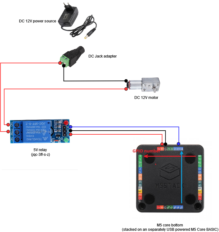
And here is the example UIFlow that works for me:
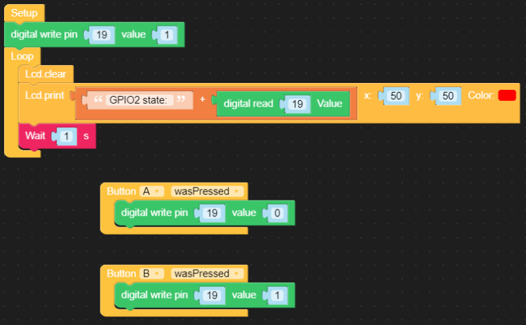
Now I need to find a way to power the M5 Core Basic by using a DC 12V --> USB 5V connector and connect it to the DC 12V power supply I already use.
Next step will be the hardest: understanding how PaHub works to interconnect the M5 Core Basic with:
- RFID reader
- M5 Scales kit
- M5 Ultrasonic Distance Unit
I will report progress here
Thank you again for your help
Best regards
-
Hi all,
Another report here.
Almost everything is ready.
I'm quite sure the RFID2 reader won't do the job because of its short reading range; let's try and improve if required.
I will certainly have to give this reader a try. (already ordered)1 question I had while testing: TOF and RFID2 seems to need Ports A or E. But Port E never worked (the unit is seen as "not connected" by the Core); forcing me to use a PaHub which is a pity because I have plenty of available ports with the ExtPort extension.
Someone able to help me understanding why ? (If I could use port E; I could completely remove the PaHub)Here is the current setup:
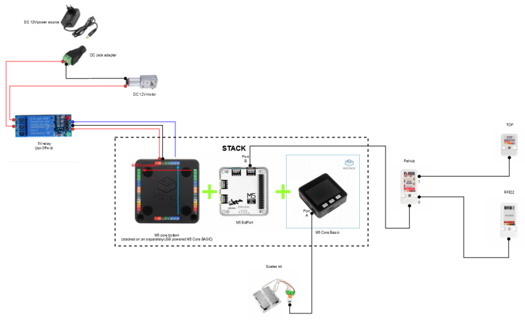
Last thing to do to complete the prototype: get a 12v --> 5V USB connector in order to power the M5 Core + 12v DC motor with a single source.
Here is a simple UIFlow to check every component works correctly:

Best regards
-
Hello all,
Last part done (single power supply for M5 core + DC motor)
I was also able to remove the PaHub by using the ExtPort (Port D). I had to change the dip switch value to:- Port D-1[2] = ON (to use GPIO22)
- Port D-2[2] = ON (to use GPIO21)
I then had to change the TOF module's port config in UIFlow to use the Port D:
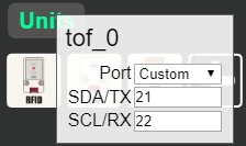
Final diagram:
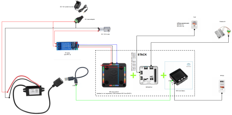
NB: DC(12v) to USB(5v) converter link
Now let's get physcal parts printed and test it !
Best regards
-
Cool and thanks for sharing your progress.
When you get everything up and running, please create a build log on Hackster.io -
Hi guys,
New problem here: I'm unable to use this RFID reader from Seeed studio
The reader is able to communicate by serial (9600 baudrate, 8 data bits, 1 stop bit, and no verify bit)
I connected it with my Ext port Blue port PortC (stacked with my M5 Core Basic)
- Reader Yellow wire (TX) --> Ext port (Port C) / PIN13
- Reader White wire (RX) --> Ext port (Port C) / PIN14
On UI Flow I tried this:
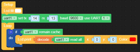
When I put an RFID tag on the reader; a red led seems to indicate it detects the tag; but I get nothing printed on my M5 Core Basic screen.
What did I wong ?
Thank you for your help
Best regards
-
Hello,
Anybody here to help me on this blocking point?
Thank you
Best regards -
@ajb2k3 hello,
I would be really happy to share my project; but for this I will need some help on my last question on this topic 😉
Any suggestion to unblock me ?
Best regards -
Have you got a micropython library installed for the reader?
It looks like you set up the connection but you have yet to initialise the reader and tell it to start talking. -
Hello,
Thank you for your feedback.
The code generated by the UIflow example from my last screenshot is the following:
from m5stack import *
from m5ui import *
from uiflow import *setScreenColor(0x222222)
lcd.fill(0xffffff)
uart1 = machine.UART(1, tx=14, rx=13)
uart1.init(9600, bits=8, parity=None, stop=1)
while True:
if uart1.any():
lcd.print((uart1.read()).decode(), 0, 0, 0xff0000)
wait_ms(2)Do I need to add something else to this code to receive any signal from the reader ?
Do tyou mean UIFlow requires additional libraries to be able to communicate over serial (UART) ?
Thank you for your help
Best regards -
Hello @ajb2k3
I took a look on your UIFlow handbook for some examples on serial communication.
I found this:
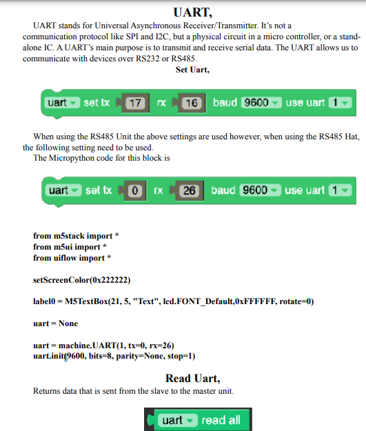
It seems the code is almost the same than the one generated for me by UIFlow.
The imported libraries are the same than the ones I have in my code:
from m5stack import
from m5ui import
from uiflow importOn the example provided by my reader's provider; they import this library: " #include <SoftwareSerial.h>"
https://wiki.seeedstudio.com/Grove-125KHz_RFID_Reader/#play-with-arduino
But I think this is the implémentation for Arduino and I guess the equivalent UIFlow libraries are loaded through this:
from m5stack import
from m5ui import
from uiflow importDo I miss something ?
On my side I think the reader works because when I bring a RFID tag close to it; the status led of the reader lights up.
But I still receive nothing on the M5 core RX PINThank you for your help
Best regards