This article is republished from Tatsushi Matsubayashi [1] of ALBERT Inc.[2]
Link:https://blog.albert2005.co.jp/2023/03/28/isaac-gym-mycobot/
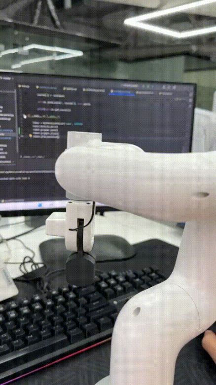
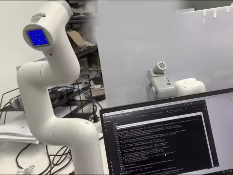
Greetings, I am from the Advanced Technology Department. Following our previous blog post titled "Controlling myCobot using RealSense D455 for Spatial Recognition", I will now introduce an experiment utilizing myCobot. This time, the experiment will be conducted using a simulator rather than a physical machine. When attempting deep reinforcement learning with robots, it can be challenging to prepare large amounts of training data on a physical machine. However, with a simulator, it is easy to collect massive datasets. Nevertheless, simulators may appear daunting to those who are unfamiliar with them. Therefore, we tried using Isaac Gym, developed by Nvidia, which allowed us to achieve everything from creating an experimental environment to conducting reinforcement learning with almost nothing but Python code. In this post, I will introduce the method we used.
- Introduction
1.1 What is Isaac Gym?
Isaac Gym is a physics simulation environment developed by Nvidia for reinforcement learning. Based on the OpenAI Gym library, the physics calculations are performed on the GPU and the results can be received as Pytorch GPU tensors, enabling fast simulation and learning. Physics simulation is carried out using PhysX, and it also supports soft body simulation using FleX (although some features are limited when using FleX).
The latest version as of January 2023 is Preview4. While earlier versions had noticeable bugs, versions 3 and onwards have seen improvements and added functionality, making it a very attractive simulation environment. A future release of Omniverse Isaac Gym, integrated with Isaac Sim, is planned. However, Isaac Gym itself is standalone and can be used for experiments in Python. In a previous blog post ("GPU Server Expansion and A6000 Benchmarking"), it was mentioned that research and development using Omniverse Isaac Simulator had begun, but Isaac Gym was prioritized for reinforcement learning simulation. The biggest benefit of integrating Isaac Gym with Omniverse would likely be the ability to use photorealistic visuals for image recognition and high-precision continuous body simulation, such as with ray tracing. It will be exciting to see how this develops in the future.
PhysX is a physics engine developed by Nvidia, enabling real-time physics calculations on the simulator's GPU. Although the version used by Isaac Gym has not been specified in publicly available arXiv or documentation, it is likely based on PhysX 4, given its release timing and separation from FleX. In Omniverse, PhysX 5 is used and FleX is integrated as well.
FleX is also a physics engine developed by Nvidia, but it enables the representation of soft bodies and fluids using particle-based simulation, in contrast to PhysX's rigid body simulation.
1.2 Purpose of this article
I will tell you how I was able to easily create and learn reinforcement learning tasks using Isaac Gym. As an actual test case, I will introduce an object grasping task created by importing myCobot introduced in the previous article into the simulation environment.
https://blog.albert2005.co.jp/2022/12/21/realsense-d455_mycobot/
1.3 Environment
PC1: Ubuntu 20.04, Python 3.8.10, Nvidia RTX A6000
PC2: Ubuntu 18.04, Python 3.8.0, Nvidia RTX 3060Ti
Please note that Nvidia Driver 470 or later is required.
2.Install
In this chapter, we will install Isaac Gym and IsaacGymEnvs. The recommended environment is Ubuntu 18.04, 20.04, Python 3.6~3.8, and Nvidia Driver==470. Please note that since python_requires<3.9 is described in Isaac Gym's setup.py, it cannot be used as is for versions 3.9 and above. Testing has not been performed on Ubuntu 22.04, but it is probably okay.
2.1 Isaac Gym
You can download the Isaac Gym main package for free from Nvidia's developer page. The documentation is saved in HTML format in the "docs" directory of the package (please note that it is not available on the website). After downloading, you can install it with the following command:
$ cd isaacgym/python$ pip install -e .
However, since PyTorch is specified as "torch ==1.8.0" and "torchvision ==0.9.0", you should install it first from the official page that matches your environment when using your GPU. Docker and Conda virtual environment setup files are also available. Since I use venv to manage my Python virtual environment, I will proceed with pip. Please note that I have written ">" in full-width characters due to a code block issue
2.2 IsaacGymEnvs
IsaacGymEnvs is a Python package for benchmark testing reinforcement learning environments in Isaac Gym. By referring to the implemented tasks, one can easily construct reinforcement learning environments using the reinforcement learning algorithms implemented in rl-games. Even for those who plan to write their own reinforcement learning algorithms, it is recommended to try learning with Isaac Gym using this package. Originally included in Isaac Gym, it was separated in Preview3 and is now publicly available on GitHub.
$ git clone https://github.com/NVIDIA-Omniverse/IsaacGymEnvs.git
$ cd IsaacGymEnvs$ pip install –e .
With this, the necessary installation is now complete.
- Demo
When you install Isaac Gym and take a look inside the package, you'll see that there are many sample environments available. These are also featured in the documentation, but in this article, we'll highlight some of the samples that are relevant to creating custom reinforcement learning environments in Chapter 4. If you've set up your environment, it's a good idea to try running some of these samples and see what they can do. You might even find that they provide some guidance on how to use the API to accomplish things you're interested in trying out (and if you're still not sure, don't hesitate to read through the documentation).
3.1. Isaac Gym
As of Preview4, there are 27 sample environments available.
● "1080_balls_of_solitude.py"
The "1080_balls_of_solitude.py" script generates a pyramid-shaped group of balls that fall down. Running the script without options only allows collisions between balls within the same environment (i.e. within the same pyramid). The "--all_collisions" option enables collisions with balls from other environments, while the "--no_collisions" option disables collisions between objects within the same environment. This script also demonstrates how to configure the arguments of the "create_actor" function to add objects to the environment.
● "dof_controls.py"
This script features an actor that moves in 3D, which is a variation of the well-known Cartpole problem in OpenAI Gym. It demonstrates how to set the control methods for each degree of freedom (DOF) of the robot, which can be either position, velocity, or force. Once set, these control methods cannot be changed during simulation, and the actor can only be controlled through the selected methods. Forgetting to set these control methods can cause the actor to fail to move.
● ”franka_nut_bolt_ik_osc.py“
This script showcases Franka Robotics' multi-jointed robot arm Panda picking up a nut and screwing it onto a bolt. The arm is controlled using inverse kinematics (IK). The file name includes "OSC, " but OSC control is not implemented in this script. However, the script "franka_cube_ik_osc.py" includes OSC control.
With the addition of SDF collision in Preview4, high-resolution collision file loading is possible, allowing for precise collision calculations between the nut and bolt grooves (Figure 1). While the initial SDF loading can take some time, subsequent loads are cached and will start quickly.
Figure 1: Simulation of a panda arm driving a nut onto a bolt
● interop_torch.py
This script shows how to use the function get_camera_image_gpu_tensor to directly obtain sensor data from the camera on the GPU. The obtained data can be output as an image file using OpenCV, just like a regular physical camera. When executed, the script creates a directory called interop_images and saves the camera images there. Since simulation data is not exchanged between the GPU and CPU, fast image processing is possible. However, if using a multi-GPU environment, an error may occur. One solution suggested on the forum is to limit the GPU usage with CUDA_VISIBLE_DEVICES=0, but this did not work in the environment used for this script.
3.2. IsaacGymEnvs
There are 14 reinforcement learning tasks implemented, and benchmark tests can be performed using the scripts in the tasks directory.
● About the configuration file
A configuration file written in YAML is prepared for each task. Common settings are in the config.yaml in the cfg directory, and settings can be changed without changing the YAML file with command line options using Hydra. The detailed settings for each task environment and PhysX are stored in the cfg/task/ directory, and the algorithm selection and structure are stored in the cfg/train/ directory.
● About algorithm implementation
The reinforcement learning algorithm uses the PPO implementation in Rl-games. Although the docs/rl_examples.md mentions the option to select SAC, it is not currently included in the repository.
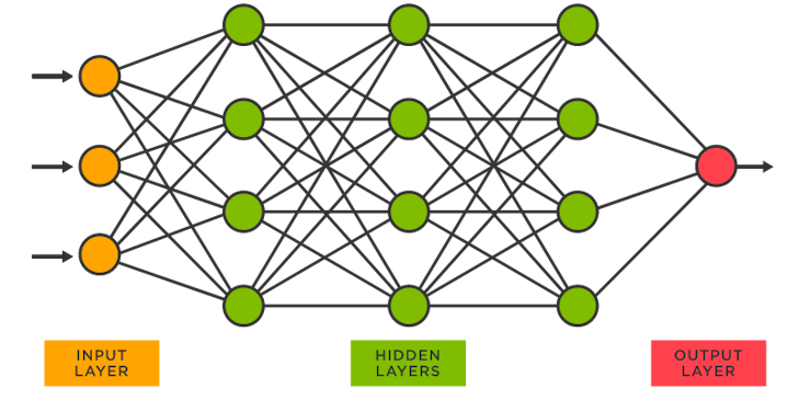
NN layers are typically MLPs, and some models also include LSTM layers as RNN layers. Although CNN layers can also be added, there are no sample models with CNN layers included. In section 5.2, we will discuss our experience adding CNN layers to a model.
The sample code can be executed in the isaacgymenvs directory where train.py is located.
● Cartpole
python train.py task=Cartpole [options]
This is the classic cartpole task where the goal is to move the cart in a way that the pole does not fall. By default, the model is trained for 100 epochs, which takes about 2 minutes on a PC2 RTX 3060Ti environment, and only 15 seconds in headless mode (without the viewer). When testing the model with inference, it performs well and the pole remains upright (after 30 epochs of training, the model is sufficiently trained to keep the pole upright). Although it may seem simple, the fact that the model can learn to complete this task successfully is reassuring.
● Franka Cube Stack
python train.py task=FrankaCubeStack [options]
This is a task where a Panda arm is used to stack boxes. The joint movements of the 7-axis arm are learned step by step. The default setting is 10, 000 epochs, but the arm movements can be learned in about 1, 000 epochs. On a PC1 RTX A6000 environment, 1, 000 epochs of training took about 20-30 minutes to complete. Figures 2 and 3 show the before and after states of the arm, where it goes from randomly moving to successfully grabbing and stacking boxes.
The action space consists of 7 dimensions for the arm joints, while the observation space is a total of 26 dimensions. The reward function is designed to scale differently for actions that involve getting closer to the box, lifting the box, moving the boxes closer to each other, and successfully completing the stacking task.
It's surprising how easily the arm can learn this level of task. However, it's important to note that the learning assumes a defined world coordinate system and the known positions and orientations of the objects. Therefore, applying this learned behavior to a physical robot may not be as straightforward.
Breakdown of 26-dimensional observation:
● 7 dimensions for the position and orientation of the box being moved
● 3 dimensions for the vector from the box being stacked to the box being moved
● 7 dimensions for the gripper's grasp position and orientation
● 9 dimensions for the arm joints and gripper fingers
Figure 2: FrankaCubeStack before training
Figure 3: FrankaCubeStack after training
Some common options in train.py are:
● headless (default: False): When set to True, the viewer is not launched. This is useful for heavy training or when capturing camera images, as the viewer can slow down the process significantly.
● test (default: False): When set to True, the learning mode is turned off, allowing you to run the environment without training. This is useful for environment generation and checking the learning results.
● checkpoint (default: ''): Specifies the PyTorch weight file to load. The learning results are saved in runs/<task name>/nn/<task name>.pth, and this option is used for resuming training or testing.
● num_envs (default: int): Specifies the number of parallel learning environments. It's important to set an appropriate number to avoid heavy viewers during testing (this option can also be set during training, but changing it can cause errors due to batch size and interference).
Note that train.py configures horizon_length and minibatch_size, but batch_size = horizon_length * num_actors * num_agents, and batch_size must be divisible by minibatch_size. Additionally, num_actors and num_agents are proportional to num_envs, so changing only num_envs can cause errors.
Other samples can be tried easily with just the environment, so give them a try for some interesting tests.
3.3 Viewer Tips
● Drawing a collision mesh
The simulator usually renders an object's visual mesh, but in Isaac Gym's Viewer, you can change it to render the collision mesh instead. To do this, go to the Viewer tab in the menu window and check "Render collision meshes". If an object is behaving strangely, it's a good idea to check if the collision mesh is loaded correctly (sometimes the visual and collision meshes have different orientations, or the mesh may not have loaded correctly or with enough detail in the simulator).
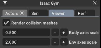
Figure 4: Drawing the collision mesh
● Reduce drawing environment
You can reduce the rendering environment to only one without changing any settings. By checking "Show only selected env" in the Actors menu, as shown in Figure 5, only the selected environment will be displayed. If there are any strange behaviors, you can debug by outputting the environment number and only rendering that environment. This also lightens the rendering load and can increase FPS.
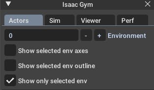
Figure 5: Numbering the drawing environment
● Change initial camera position
The initial camera position and orientation can be set using gymapi's viewer_camera_look_at(viewer, middle_env, cam_pos, cam_target). In task scripts for training, you need to override the set_viewer function to make changes.
- Original environment and task creation
It's finally time to create the original task for the main subject.
4.1. Preparation
Prepare the script and configuration files. The goal is to learn a simple task of lifting a box, using Mycobot for object picking. Therefore, we will proceed with creating a task named "MycobotPicking". We need three files:
● tasks: the main Python script
● cfg/task: YAML configuration file for environment and simulation parameters
● cfg/train: YAML configuration file for learning algorithms, neural network layers, and parameters.
We can refer to the "FrankaCubeStack" task mentioned earlier and create these files accordingly. The configuration files are especially important and we can copy and modify them according to our requirements.
As shown in the demo, we can load the task script from the train.py file using command-line options. Therefore, we need to add an import statement for the task class in the init.py file in the tasks directory, along with the task name when passing arguments.
4.2. Environment Creation
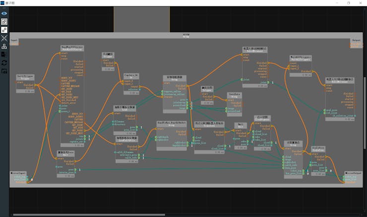
The task class is created by inheriting from the VecTask class in the tasks/base directory, and the task has the following structure as shown in Figure 6.

Figure 6: Task configuration. Those with an orange frame do not need to be edited, and those with a green frame are created for each task.
4.2.1. init processing
- Creating Simulator and Environment
● create_sim: This function generates an instance of the simulator. The process itself is defined in the parent class, and the properties are set in the config file, such as gravity and step time. Similar to FrankaCubeStack, the function uses the following two functions to generate the ground plane and the actor.
● create_ground_plane: This function generates a ground plane by inputting the normal direction of the plane. If you want to create an uneven terrain, you can refer to the terrain_creation example.
● create_envs: This function loads and sets properties for the actor file, generates the actor and parallelizes the environment. In this task, we generated myCobot from the URDF and the target object from the create_box API. The URDF of myCobot was based on the one used in the previous experiment with MoveIt, and we added a gripper for picking (details about the gripper are explained in section 5.1).
- Data Initialization
● init_data: This function defines environment variables from the config file and prepares a buffer for data tensors processed by Isaac Gym (PhysX). The necessary data for calculating state and reward is defined as class variables. The API loads the tensor data into the buffer, which is updated every step by calling the corresponding refresh function.
4.2.2. processing steps
- Step Processing:
The main step function is defined in the parent class and does not need to be modified. However, the following two steps are necessary as abstract methods:
● pre_physics_step: Manipulate the actor using the action. The size of the action is defined in the config as [“env”][“numActions”]. For myCobot's 6-axis arm and gripper, we set it to 7 dimensions.
● post_physics_step: Calculate the observation and reward. Also check whether to reset the environment. We set it to reset after reaching a maximum of 500 steps or a successful lift.
The step order is fixed to apply action → physics simulation → calculation of observation and reward to pass data for learning. Even if you only write "pass" here, you can check the environment while starting the viewer.
● reset_idx: Returns the environment to its initial state. Of course, the randomness of the initial state is closely related to the generalization of learning. We set myCobot to the initial posture and randomly reset the position of the target object within myCobot's reachable range.
- State and Reward Calculation:
● compute_observation: Update each buffer with the refresh function and put the desired state in the obs_buf. The size of obs_buf is defined in the config as [“env”][“numObservation”].
● compute_reward: Calculate the reward. As the gripper approaches the target object's grip position (between the fingers), a reward is obtained, and a larger reward is obtained as the height of the target object increases.
4.3. Execution of training
Now that the task framework has been created, let's train the model. We can start training the model using the following command:
python train.py task=MycobotPicking --headless
After 200 epochs, the initial weights will be saved, and new weights will be saved if the reward improves. However, the task we created may not work perfectly, and the training process may stop progressing quickly. In the following section, I will discuss the adjustments I made to the task to improve its performance.
4.4. Task Coordination
By using the learned weights to test, you can debug why the training did not work well. You ran the command
python train.py task=MycobotPicking test=True checkpoint=runs/MycobotPicking/nn/[checkpoint].pth
to test your model. However, you encountered issues with your gripper not moving well. Despite your efforts to resolve the issue, you concluded that the URDF did not support closed-loop structures, making it difficult to simulate the gripper's movements accurately. As a result, you decided to use a rule-based approach to control the gripper's closing and lifting actions. You fixed the gripper's fingers to a fixed link and reduced the action space from 7 to 6 dimensions. You also noted that when using a simulator to control a robot arm, it is better to use a gripper without closed loops, such as the Panda arm.
Another issue you faced was that the agent stopped approaching the object at a certain distance and hesitated to touch it, resulting in lower rewards. You modified the reward system by increasing the reward function's value with a threshold distance as a step function, maximizing the reward when the agent reached the target point. You also removed the environment reset after task completion, as it caused the agent to stop learning before reaching the actual goal. Instead, you adjusted the maximum number of steps to the necessary number for task completion, improving the learning speed.
You also found that penalizing difficult tasks too harshly made the reinforcement learning agent too conservative. This gave the agent a more human-like personality, making the learning process more interesting. Finally, you encountered a similar phenomenon in the FrankaCabinet benchmark task, where the agent would stop learning after pulling the drawer to a certain distance, even though a higher reward was available for fully pulling it out. You did not fix this issue, but instead, you removed the environment reset after task completion and adjusted the maximum number of steps to complete the task smoothly.
Figure 7: myCobot keeps away from objects
The self-collision of the arm was being ignored. Although I was able to reach the desired position, the arm was now in a position where self-collision was completely ignored, like a figure-eight. I tried to research whether it was possible to set up self-collision calculation in the documentation, but it didn't work well. In the first place, it is not realistic that all joint angle limits in the provided URDF are set to -3.14~3.14, so I decided to adjust the upper and lower limits of each joint angle to avoid self-collision. The reason why the joint angles moved to the largest possible values is still unknown.
Figure 8: myCobot that ignores the accident collision
The arm doesn't stop exactly where it's supposed to and instead wobbles around it. We wanted the action to approach 0 as it reached the target position, but it was difficult to achieve, and the arm kept vibrating around the target position. We tried penalizing the action and adjusting the reward by setting the target position precisely, but it didn't improve the results. We decided not to worry about this issue as it could be handled by rule-based control during actual operation.
Although it was not a must-have, we wanted the gripper to be downward facing for better appearance. So, we added a penalty term to the reward function that penalized the gripper angle. Figure 9 shows the learning results before fine-tuning.
Figure 9: MyCobot after learning before fine-tuning
The result of the adjustments mentioned above is shown in Figure 10. If this level of accuracy can be achieved on the actual robot, it should be capable of lifting objects sufficiently.
Figure 10: MyCobot after training after fine-tuning
- Others
I will introduce the story that was not good and the story that I want to try.
5.1. The story of a homemade URDF gripper that didn't work
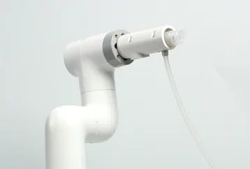
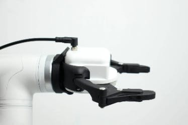
The URDF of myCobot was based on the one used in the previous attempt to move the actual robot, but it did not include the gripper. Although there was a gripper model available on the official GitHub page, it only provided a DAE file with a visual representation as shown in Figure 11(a). To create a URDF that can be used in a simulator, separate 3D models for each joint part are required. Therefore, using Blender, we divided the parts by joint (Figure 11(c)) and created simplified box-shaped parts for collisions since it is difficult to reproduce complex shapes (Figure 11(b)). Then, we described the structure of the links and joints in the URDF file to complete the model. However, since URDF does not support models with open link structures, we removed the collision from one of the links on the base and completed the joint with the fingertip side. Although this method is rough, we were able to reproduce the movement of the actual robot in the simulator by moving the six joints at the same angle. Figure 11(d) shows a comparison between the completed model and the actual robot (using the provided model, but the details are quite different). However, when we actually tried to move it, as mentioned in section 4.4, it did not work well. The reason was that it was not possible to move the joints in a coordinated manner when external forces were applied (it may have been solved if torque control was properly implemented).

Figure 11: Creating a gripper for myCobot (a) Published gripper model (b) Collision model parts created according to the model (c) Visual model parts disassembled from the gripper model (d) Isaac Gym Comparison of drawing and actual gripper
5.2. Use image recognition
In benchmarks and the MycobotPicking task, we use object position and orientation information in the observations, but obtaining this information in real-world tasks is not easy. Therefore, using only 2D camera information and easily obtainable servo joint angle information for reinforcement learning would be more valuable.
We attempted to replace observations with images and use a CNN layer for learning in the FrankaCubeStack task. However, we only modified the algorithm to accept image input and as expected, the learning did not perform well. There is no framework to add the servo joint angle information as 1-dimensional data to the CNN layer, and using image information directly in the CNN layer increases the computational complexity and limits the parallelization of the environment. Additionally, we would need to tune hyperparameters such as learning rate and clip value, but we did not pursue this as the effect is not promising enough.
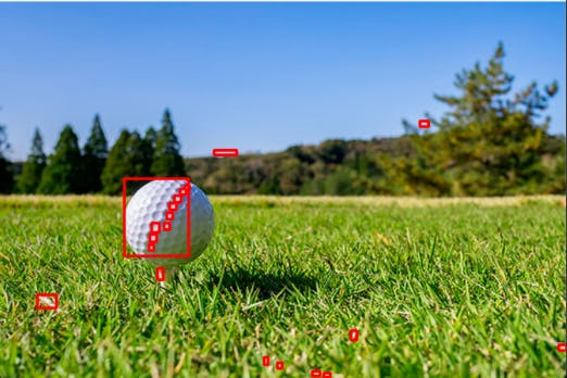
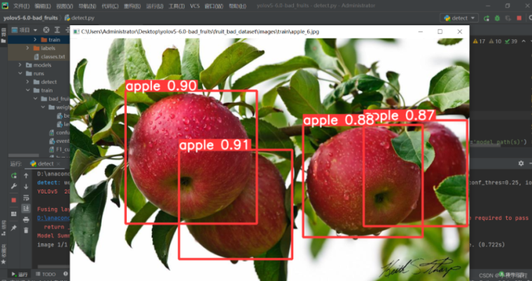
In this test, we only confirmed the method of adding the CNN layer for learning. However, it may be more effective to use transfer learning to encode features for gripper and object recognition from easy-to-use object recognition models such as YOLO or ResNet, and then use the encoded features and joint angles for reinforcement learning, rather than using CNN layers directly with camera images.
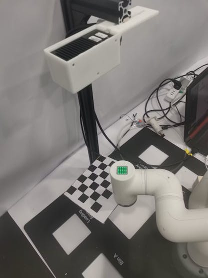
5.3. Using the Trained Model on the Actual Robot
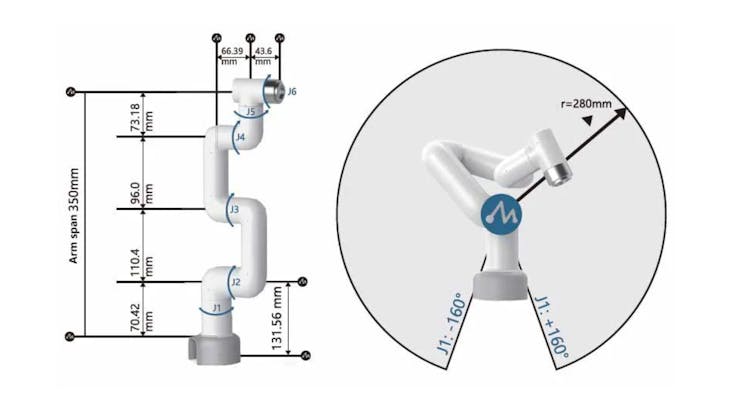
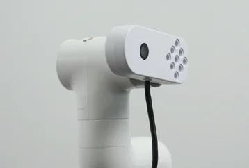
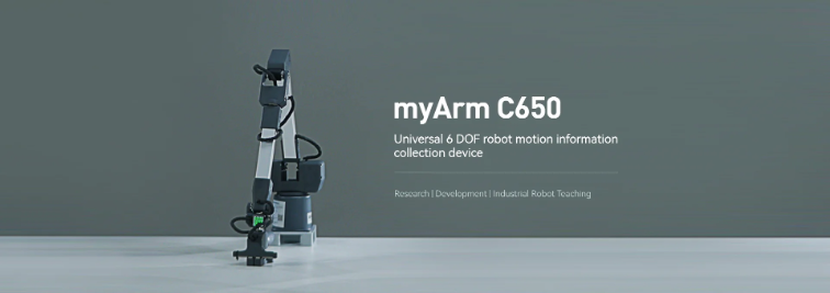
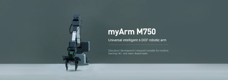
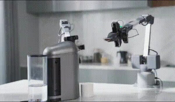
I attempted a Sim2Real experiment using the trained model and the myCobot and RealSense for spatial recognition, as mentioned in the previous article. However, it did not work well. While the reaching motion worked to some extent, the movement became unstable as it approached the object, and it was not possible to accurately move to the position to grab the object. Possible issues include the fact that the myCobot does not have enough power to move accurately to the target posture and the accumulation of small differences due to the fact that the simulator predicts the next target posture before reaching the current one, whereas the actual robot does not. Regarding the former, the myCobot used in this experiment is an inexpensive educational arm with a portable weight of 250g, so if you want to move more accurately, you should use a higher-end robot arm, such as those used in reinforcement learning for picking. Elephantrobotics, the company that makesthe myCobot, also sells models with stronger servo motors that can carry up to 1kg, so I would like to try those as well.
- Summary
This time, I created a reinforcement learning task using Isaac Gym and actually trained the model. I experienced the design of a robot reinforcement learning problem in a 3D physics simulator and the issues that arise when running the trained model. It was attractive to be able to test the learning environment without having to write the reinforcement learning algorithm from scratch. The availability of benchmark environments makes it easy to compare and verify new learning algorithms, which is a great advantage for researchers and analysts with various professional backgrounds.
ALBERT has researchers and analysts with various professional backgrounds who are ready to assist with any technical or business-related inquiries. Please feel free to contact us.
Reference
- Tatsushi Matsubayashi, 2022.12.21, Isaac Gym で myCobot の把持タスクを強化学習してみました。
https://blog.albert2005.co.jp/2023/03/28/isaac-gym-mycobot/
- ALBERT Inc. https://www.albert2005.co.jp/english/


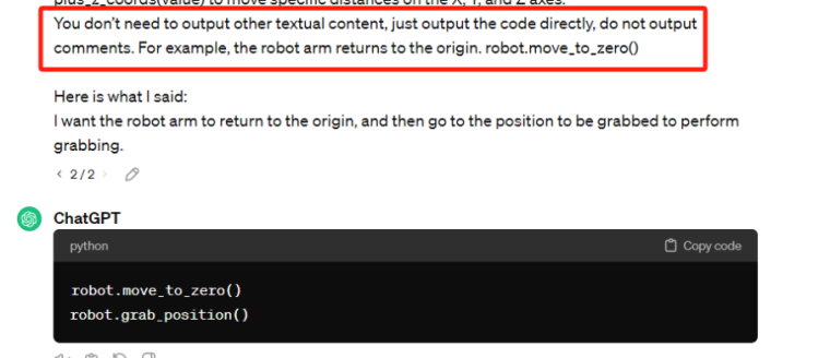
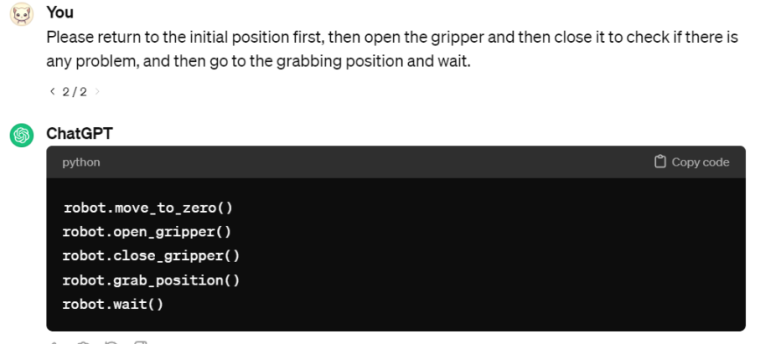 Copy the generated code and run it.