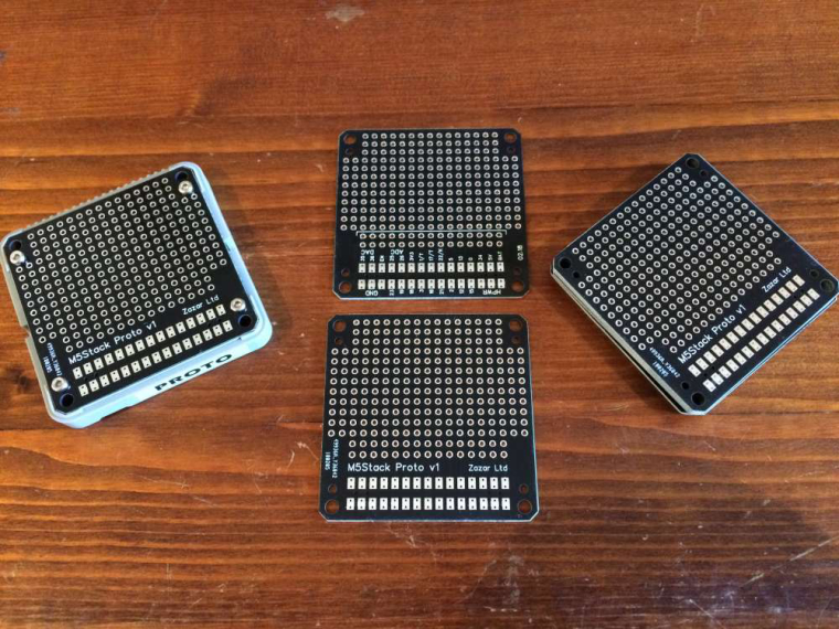
Yes, if you head over to https://easyeda.com/suremicro the design is there which you can use to get your own boards made. I used JLCPCB.
Posts made by suremicro
-
RE: Custom Prototype Boardposted in PROJECTS
-
RE: How to connect DS18B20 - Which pins are available?posted in FAQS
OneWire version 2.3.4
DallasTemperature version 3.79 -
RE: How to connect DS18B20 - Which pins are available?posted in FAQS
This is what I used just to test read multiple sensors on the M5Stack:
#include <M5Stack.h> #include <OneWire.h> #include <DallasTemperature.h> #define ONE_WIRE_BUS 5 // DS18B20 on arduino pin2 corresponds to D4 on physical board OneWire oneWire(ONE_WIRE_BUS); DallasTemperature DS18B20(&oneWire); void setup() { M5.begin(); M5.Lcd.setTextColor(TFT_WHITE,TFT_BLACK); M5.Lcd.setTextSize(2); } void loop() { float celsius; float fahrenheit; DS18B20.begin(); int count = DS18B20.getDS18Count(); //M5.Lcd.clear(); M5.Lcd.setCursor(0,0); M5.Lcd.print("Devices found: "); M5.Lcd.println(count); if (count > 0) { DS18B20.requestTemperatures(); for (int i=0; i < count; i++) { celsius = DS18B20.getTempCByIndex(i); fahrenheit = celsius * 1.8 + 32.0; celsius = round(celsius); fahrenheit = round(fahrenheit); M5.Lcd.print("Device "); M5.Lcd.print(i); M5.Lcd.print(": "); M5.Lcd.print(celsius,0); M5.Lcd.print( "C / "); M5.Lcd.print(fahrenheit,0); M5.Lcd.println("F"); } } delay(2000); } -
RE: Custom Prototype Boardposted in PROJECTS
Yes the device will be used to record multiple temperatures using DS18B20 sensors on one wire with a single 4.7k resistor. I hooked up 5 and can read them indiviudally since they have there own addresses. I only need the temperature to the nearest degree so they are fine for my purposes.
I actually use a 3.5mm jack and bought a few connectors as like you found that many do not fit, however the very small SMD mounted ones just fit in the standard case. The ones I found are on Amazon:
https://www.amazon.co.uk/dp/B008SO0E60/ref=pe_3187911_189395841_TE_3p_dp_1
-
RE: Custom Prototype Boardposted in PROJECTS
The PCB and 3D case design files can now be found on GitHub at https://github.com/zazardev/M5Stack-Proto
For those using EasyEDA see https://easyeda.com/suremicro
-
RE: Custom Prototype Boardposted in PROJECTS
I used Easy EDA which imported the pcbdoc file after some messing around with the format. I will make the gerber and pcb files files available as well as the 3D prototype enclosure file (with solid edges) soon.
I have now tried out the new board with a couple of simple jack connectors and all seems to work!

-
RE: Custom Prototype Boardposted in PROJECTS
@m5stack 在 Custom Prototype Board 中说:
.

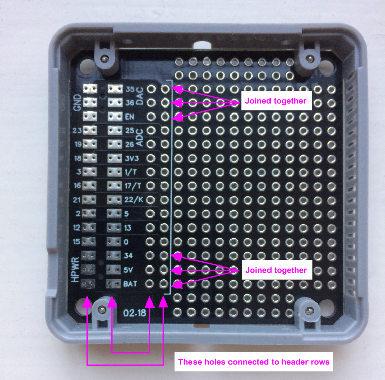
I've just received the headers, which seem to be custom parts so they're not readily available which is a shame (and expensive since they only ship them with a module or core). Once they have been soldered I'll test them and report back - thanks for the note on DAC/ADC it's a print error the pins are the same as the main board.I have also had a few blank enclosures made, with the holes removed, in both PLS and ABS for testing.
I really like the M5Stack but it's let down by not releasing more design files (for all the enclosure parts) and having better access to custom parts such as the headers so other developers can make their own modules.
-
RE: Turn Off Displayposted in FAQS
Hi
Funny I looked at this last night - if you set the brightness down to 0 it seems to turn the display off (I still need to measure the current usage).
I added a timer in the loop so that the screen 'turned off' after a few seconds and would switch back on when the first button pressed - very simple but just a test.
-
Custom Prototype Boardposted in PROJECTS

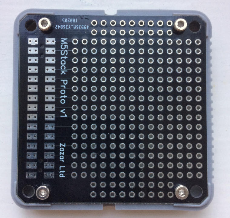
I ordered the M5Stack Proto board along with the core unit hoping to develop a working prototype that could be shown to potential users. While the board is fine I quickly realised that you couldn't use the battery back cover since wiring for the through holes would need to be connected to the female header.
This was a shame as it would make demonstrations require another power source and would show the internals underneath. So I have created my own version based on the M5Stack Proto board which fits into the shell.

The header pads are connected to to first two rows of through holes allowing you to connect into the pins and replace the battery back cover.

The pins follow the same vertical order but reversed horizontally i.e. the first header pads are connected to the second through hole. Both GND and HPWR pins are also connected and the holes tied together as with the header.
I have ordered a few sets of header pins from M5Stack which should arrive this week and then test to see if it works. The spacing of the tracks for the first header row are outside production tolerrance, however I will be only connecting a few pins at a time and it is for development purposes only.
-
RE: Board header pin part numbersposted in PRODUCTS
Thanks JimiT, I saw these for sale but it says
"Pay Attention: Dear Customers, If you want to buy these connectors, please order together with our Core Development Kits or Functional Modules. We'll not arrange shipment if just order this only. Thanks for your kind cooperation."
which confused me, I'll try an order ;)
-
Board header pin part numbersposted in PRODUCTS
Hi
Can you give the part numbers for the male and female headers used in the expansion boards. I understand you supply these but require a core module to be purchased, and I don't really want to buy another just for the extra headers.
Thanks